Hello,
I am looking for a proven transistor based 50-100 watt solid state amplifier (class a/b) schematics. Looking for a proven design that won't break a bank but will sound good. I am going to be using it with my diy 2way speaker (88db, ss9500 top end with vifa pl18wo mid).
I searched on google and this forum but found only Class A designs, but would like to find something more efficient because finding large heatsinks and large transformer is going to be a hassle.
tia
Jean
Here's a few links I have found...
http://www.mhennessy.f9.co.uk/
http://www.neilmcbride.co.uk/ <- the one I'm saving up for (look at 'Naim style amps')
http://steve.sky.net.ua/a_index.htm <- loads of stuff
http://users.ece.gatech.edu/~mleach/lowtim/
http://sound.westhost.com/index.html <- quite a lot as well
Hope it helps.")
- Stu -
http://www.mhennessy.f9.co.uk/
http://www.neilmcbride.co.uk/ <- the one I'm saving up for (look at 'Naim style amps')
http://steve.sky.net.ua/a_index.htm <- loads of stuff
http://users.ece.gatech.edu/~mleach/lowtim/
http://sound.westhost.com/index.html <- quite a lot as well
Hope it helps.
- Stu -
Hey,
What about the AKSA?
Try www.printedelectronics.com
I should mention I have a vested interest ; I am the designer, and this is a kitset, available as either a 55W or a 100W, complete with heatsinks, but not transformers or case.
Cheers,
Hugh
What about the AKSA?
Try www.printedelectronics.com
I should mention I have a vested interest ; I am the designer, and this is a kitset, available as either a 55W or a 100W, complete with heatsinks, but not transformers or case.
Cheers,
Hugh
Hello Hugh,
Your AKSA kit looks very tempting, with complete finished circuit boards and even supplied heatsinks. I wasn't exactly looking for a complete ready to go kit like yours, but it does look interesting I might just get that unless I find something else more "challenging" (when I have to drive all around town to find the components I need, but thats part of the fun in building something like a good amp).
thanks though, you might hear from me
Jean.
P.S. the following link doesn't work http://www.printedelectronics.com/pe/products/heatsinks/Conrad.htm
Your AKSA kit looks very tempting, with complete finished circuit boards and even supplied heatsinks. I wasn't exactly looking for a complete ready to go kit like yours, but it does look interesting
I might just get that unless I find something else more "challenging" (when I have to drive all around town to find the components I need, but thats part of the fun in building something like a good amp). thanks though, you might hear from me
Jean.
P.S. the following link doesn't work http://www.printedelectronics.com/pe/products/heatsinks/Conrad.htm
Project 3A
If I were you I'd stop searching and I'd take a look at this awesome amp (ESP project 3A) Search around this amp on the forum I guarantee you'll find nothing but good reviews from DIY'ers.
-Simon
If I were you I'd stop searching and I'd take a look at this awesome amp (ESP project 3A) Search around this amp on the forum I guarantee you'll find nothing but good reviews from DIY'ers.
-Simon
Although I can't compare project 3A to ASKA nor Leach (haven't build those yet)... IMHO 3A is the perfect amp project for anyone who wants to give a try at DIY and expect to build something powerfull and yet verry stable.
Straight forward amp, no costly or rare component to buy, flexible design, great sound... as it all!
My version of this amplifier hasen't encountered major problem since i finished assembling it. Although I designed my own pcb the sound is awesome and there is no sign of evil oscillation. The only problem with this simple design is that you can't short output terminals with out cooking your transistors.
Just ask if you have anymore questions
-Simon
Hi Simon,
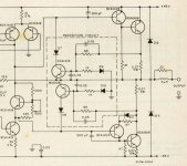
If you really want to protect your amp against short ciruits at the output, you can simply add a protection circuit to the schematic, it's really simple (about 5 components per channel). OK, there are a few guys on this forum who doesn't like such circuits, because some believe they will have influence on the output signal of the amp. I don't see any reason why such a circuit will do that (under normal conditions of course). DON'T use fuses to protect your transistors, they are simply too slow to handle short circuits.
You can see an example in the included figure.
best regards,
HB.
The only problem with this simple design is that you can't short output terminals with out cooking your transistors.
If you really want to protect your amp against short ciruits at the output, you can simply add a protection circuit to the schematic, it's really simple (about 5 components per channel). OK, there are a few guys on this forum who doesn't like such circuits, because some believe they will have influence on the output signal of the amp. I don't see any reason why such a circuit will do that (under normal conditions of course). DON'T use fuses to protect your transistors, they are simply too slow to handle short circuits.
You can see an example in the included figure.
best regards,
HB.
Attachments
Jean-
This is the amplifier, fitted 2 of them in this small case.
capacitors are Nippon Chemi 6800uf X4 (you could go for a bigger value)
Transformer is a 350VA EI core salvaged from an old amp
(I'D suggest you go with toroidal tranny, less noise and smaller size.)
Heatsinks don't need to be that big, depends on how hard you want to push this amp. I coulden't use bigger heatsink because of the small size of the case so I installed cpu cooling fan on both HS. Anyway, better to overkill then to melt your OP transistors.
Verry simple layout as you can see
Vivek- If you're talking about point-to-point wiring then I have no idea what the final results may be. I assume that as long as you keep conductors big enuff your only worry would then be oscillation and outside noise.
-Simon
An externally hosted image should be here but it was not working when we last tested it.
This is the amplifier, fitted 2 of them in this small case.
An externally hosted image should be here but it was not working when we last tested it.
capacitors are Nippon Chemi 6800uf X4 (you could go for a bigger value)
Transformer is a 350VA EI core salvaged from an old amp
(I'D suggest you go with toroidal tranny, less noise and smaller size.)
An externally hosted image should be here but it was not working when we last tested it.
An externally hosted image should be here but it was not working when we last tested it.
Heatsinks don't need to be that big, depends on how hard you want to push this amp. I coulden't use bigger heatsink because of the small size of the case so I installed cpu cooling fan on both HS. Anyway, better to overkill then to melt your OP transistors.
An externally hosted image should be here but it was not working when we last tested it.
Verry simple layout as you can see
Vivek- If you're talking about point-to-point wiring then I have no idea what the final results may be. I assume that as long as you keep conductors big enuff your only worry would then be oscillation and outside noise.
-Simon
Simon - very nice! but is it just me or the picture shows power caps are dented on the sides ? Is that 8ga power wire that you used ?
sam9 - thank you! I like this heatsink http://www.sealelectronics.com/kits/images/400w-1.jpg
jean
sam9 - thank you! I like this heatsink http://www.sealelectronics.com/kits/images/400w-1.jpg
jean
Jean- The cap are in fact dented, I beleive that they were built that way, they're rugged devices and cheap ones too (3.95$cnd a peice).
The wiring is 10ga, possibly too much but nothing's wrong with too much.
Palesha- For the schematic I took the original project 3A as is on ESP website and for the layout I'll accept any good offer
-Simon
The wiring is 10ga, possibly too much but nothing's wrong with too much.
Palesha- For the schematic I took the original project 3A as is on ESP website and for the layout I'll accept any good offer
-Simon
Hugo,
I understand that you do not see because protection circuits cause sound impairment. But it is a fact, which is clearly audible, by listening to music, with superior quality source and loudspeaker : transients are rough, hoarse. Protection of high end audio amplifiers is a complex problem.
Regards, P.Lacombe
Well I ordered all the components from Mouser and Futurlec. Just need to order transformer (s) and power supply caps. I was looking at Polymer Aluminum capacitors , page 327-329 .
http://www.mouser.com/catalog/cat_610/327.pdf
http://www.mouser.com/catalog/cat_610/328.pdf
http://www.mouser.com/catalog/cat_610/329.pdf
How good are they? reliable ? What else is out there for under $25 a cap ?
Thanks
http://www.mouser.com/catalog/cat_610/327.pdf
http://www.mouser.com/catalog/cat_610/328.pdf
http://www.mouser.com/catalog/cat_610/329.pdf
How good are they? reliable ? What else is out there for under $25 a cap ?
Thanks
- Status
- This old topic is closed. If you want to reopen this topic, contact a moderator using the "Report Post" button.
- Home
- Amplifiers
- Solid State
- 50-100watt amplifier schematics wanted