I have read with some interesting comments on the high output impedance of output stages using common emitter or common source circuits. These of course use the collector or drain as the output instead of the emitter or source.
One person commented that nobody uses the common source configuration. This of course is an error in thinking. All of my amplifier designs for example use common source configuration. Naturally the output impedance of these and designs that may be similar circuits are going to have higher output impedances than those using common drain configuration. This rise in output impedance is primarily due to the fact that the common source configuration does not use 100 percent negative self-feedback in the output stage that a source or emitter follower configuration has. The great benefit of using a common source configuration in a amplifier that drives a loudspeaker is that you gain the ability to control the output impedance via a selected amount of negative feedback around the stage. This is because the restriction of 100 percent self-negative feedback is gone. This has some major benefits when one wishes to achieve maximum performance when driving loudspeakers..
Many persons have been lead to believe that an audio power amplifier must have very low output impedance and thus able to provide high damping factors. This line of thinking is incorrect in my opinion since it totally disregards what it takes to make loudspeakers perform the best. There are designs that actually include positive current feedback to achieve near zero output impedance over a good portion of their operating range.
If one has the ability to adjust the output impedance while listening to music played though your favorite loudspeakers you may find that output impedances between .2 and .5 ohms actually provide the best sound quality. And also that low feedback factors around the output stage in the order of 6 to 15 Db are best. This should provide damping factors in the order of 12 to 20 and is similar to what a tube amplifier would provide. Feedback factors of 6 to 15 Db cannot be achieved with circuits that use a source follower in the output stage since they run at close to 100 percent negative feedback already.
The source follower output stage is more popular for two main reasons. It is easy to use and second it has lower distortion. Unfortunately the low distortion and thus its linearity is provided by 100 percent negative feedback. Considering that negative feedback is undesirable in such large amounts makes me wonder why the configuration is used at all to drive loudspeakers.
For every one who is seeking the sound of a tube amplifer in a solid state design the first thing you have to get rid of is the source follower in the output stage. Then adjust the negative feedback around the output stage to reasonable values.
John Fassotte
Alaskan Audio
alaskanaudio said:The great benefit of using a common source configuration in a amplifier that drives a loudspeaker is that you gain the ability to control the output impedance via a selected amount of negative feedback around the stage. This is because the restriction of 100 percent self-negative feedback is gone.
The source follower output stage is more popular for two main reasons. It is easy to use and second it has lower distortion. Unfortunately the low distortion and thus its linearity is provided by 100 percent negative feedback. Considering that negative feedback is undesirable in such large amounts makes me wonder why the configuration is used at all to drive loudspeakers.
Another benefit of a common source output stage is that it can swing virtually from rail to rail, something a bipolar follower and especially a mosfet follower can't touch without bootstrapping the drive.
Negative feedback is only undesirable in combination with it's enemy phase shift. If you had an amp with no phase shift or signal path delay you could wind up the feedback all you wanted and it would sound great, but it is phase shift and similar things that make nfb look bad because it lures it over to the dark side and it becomes positive feedback or part thereof.
An emitter follower can tolerate 100% nfb because phase shift is virtually nonexistent in that one stage. Try it over several stages and that's when the wheels fall off.
GP.
With BJT stage i think that there is a small problem when working in emitter follower.
1) You do have phase shift but it is at a much higher frequency.
2) The biggest problem i have discovered lately when designing a NFB amp is that when driving a capacitive load where the current is 90 degress ahead of the voltage you would be able to see this at the bases of the BJT!. Which mean that you turn the phase of the previous stage too much when the idle "current or outputimpedance" of the previous stage is too "low or high"!!! That will make a lot of trouble in a NFB amp.
")
Here i think the common emitter/source has some great benefit because of the load placement in the signal path. The load is no longer part of "gm" stage wich make up the voltage-current conversion.
Can you follow me?
Sonny
1) You do have phase shift but it is at a much higher frequency.
2) The biggest problem i have discovered lately when designing a NFB amp is that when driving a capacitive load where the current is 90 degress ahead of the voltage you would be able to see this at the bases of the BJT!. Which mean that you turn the phase of the previous stage too much when the idle "current or outputimpedance" of the previous stage is too "low or high"!!! That will make a lot of trouble in a NFB amp.
Here i think the common emitter/source has some great benefit because of the load placement in the signal path. The load is no longer part of "gm" stage wich make up the voltage-current conversion.
Can you follow me?
Sonny
A couple of questions,
The open loop output impedance of a common source/emitter output stage will be very high meaning that when connected to a reactive load the gain of the output stage will change with varying load impedances. Therefore with any given loudspeaker the level of global feedback will be quite variable and also frequency dependent, depending on what the input impedance graph of the loudspeaker looks like.
Isn't this quite undesirable?
The amplifier might be a quite unstable when driving a capacative load as a result?
Also some consider only global feedback to be musically destructive while local is not. An emitter follower operates with only local feedback and thus should give better objective and subjective performance?
alaskanaudio
You are quite right, electronics world december 1999 [new class AB power amp] published a no crossover distortion, common emitter amp with a new current mode class ab driver stage. it swings rail to rail,and the ocsiloscope waveforms show no switching distortion and utterly stable into 1uf. if your interested HPotter has the schematic,and a digital camera[i have no cam or scanner] so maybe he can post them. this may sound like heresy but can we get rid of class A with all its wasteful heat and aluminum. yes, I am building a stereo amp and i'll let you know how it turns out
You are quite right, electronics world december 1999 [new class AB power amp] published a no crossover distortion, common emitter amp with a new current mode class ab driver stage. it swings rail to rail,and the ocsiloscope waveforms show no switching distortion and utterly stable into 1uf. if your interested HPotter has the schematic,and a digital camera[i have no cam or scanner] so maybe he can post them. this may sound like heresy but can we get rid of class A with all its wasteful heat and aluminum. yes, I am building a stereo amp and i'll let you know how it turns out
Sonny,
You are right. Furthermore, additionnal difficulty with BJTs is caused by the very high transconductance. This is not the case with FETs. My ears are saying that the bests results are in common collector for BJTs, and common source with FETs. Design of a high quality BJT amplifier working in class AB with common emitter output stage is a venturesome challenge. (Or very high emitter resistors are to be used...)
With BJT common emitter darlington output configuration, some low value resistor is to be connected between the bases of the drivers and ground, in order to define the overall open loop gain of the amplifier, independently of the loudspeaker impedance variations. Generally speaking, emitter follower must always be driven by a moderate impedance.
Regards, P.Lacombe.
Reference this amp of which thousand have been built:
http://sound.westhost.com/project03.htm
http://sound.westhost.com/project3a.htm
http://sound.westhost.com/project03.htm
http://sound.westhost.com/project3a.htm
I have seen a lot of excellent comments to my original post on this subject. I would likel to respond to the one by AMPMAN for now.
AMPMAN,
I’m looking forward to looking at the circuit in the article you mentioned.
In reference to class A heat:
I suspect that this amplifier you referenced likely uses BJT’s because my experience with MOSFETs is that you have to run them in class A for maximum performance, or close to 500MA of idle current per device. Thus whether we can get rid of class A or not may depend on the type of output devices used. I would certainly like to get rid of 800 or so watts of heat in my amplifiers. Its ok in the winter but in summer it can make the listening room extremely warm. But since I like MOSFET’s I live with it.
Driver stages:
No matter what circuit arrangement an amplifier uses the driver stage must be configured to drive the output devices properly. This will likely add some complexity to both the power supply, driver and other circuits, but the results are well worth it. Many amplifiers are lacking in this regard and attempt to keep things to simple. Then they likely have to depend on excessive negative feedback as a cure.
More Common emitter and common source circuits:
I would really like to see more circuits used that use the output stage running common emitter or source mode. As far as stability goes I have tested my amplifiers with all sorts of capacitive loads for .1 to 10 uf and have never had any oscillation or instability problems with them. I contribute this to multiple feedback loops instead of one over all loop. The effects of driving such a large capacitive loads at high frequencies can be seen at the output when the waveform is viewed. But no instabilitie occurs due to good phase margins.
John Fassotte
Alaskan Audio
alasakanaudio
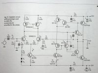
Dear sir first of all I believe in economy in all things. We should be intelectually capable of designing amps that do not waste so much power. I understand that of course, this is an ideal.Re your comments about negative feedback,I'll give you the authors view for now as I don't have a scanner. so lets begin,An important problem encountered in class-AB audio amp design concerns thebias-control loop.Often a complementry commen-collector output stage is used and the power transistors are included in the bias control loop.This can easily cause thermal instability due two the large temperature variations in the output transistors.Thermal coupling of all diodes and transistors in the class-AB control loop can improve the thermal stability of the quiescent current in the output stage. but this is in most cases too slow to react to burst signals. As a result , emitter resistors are usually added to the power transistors to improve thermal stability.However the voltage drop across the emitter resistors can switch off the transistor that is conducting the residual current.Because of the limited bandwidth of the distortion reduction by means of using negative feedback, transistor switching can be a source of high-frequency distortion. Additional circuitry is necessary to prevent this. Moreover, a common-collector stage is not able to reach a rail to rail voltage output swing due to the bass-emitter voltages. Common-emitter output stages are usually based on a complementary feedback pair. However, the local feedback loop around the pair can be a source of HF oscillation. In order to achieve thermal stability without switching problems, and to allow maximum output voltage swing, we designed a common-emitter power amplifier based on a new current-mode class-AB driver circuit. Due to the absence of local feedback at the output, the stability of the amplifier is only dependent on the global feedback-loop. The open-loop output impedance of a common-emitter amplifier is inherently high, but can be lowered by applying negative feedback. As a result, the output resistance becomes inversely proportional to the transconductance gm, and the feedback factor. Rout=1/gmB In order to obtain a closed-loop gain of 34 the feedback factor must be 1/34. For an output resistance of 30m-ohms the transconductance should be approx. 1,000A/V. This requires a cascade of at least 3 gain stages: an input transcondance stage and 2 current gain stages. end quote. Ihope this has been of use
Dear sir first of all I believe in economy in all things. We should be intelectually capable of designing amps that do not waste so much power. I understand that of course, this is an ideal.Re your comments about negative feedback,I'll give you the authors view for now as I don't have a scanner. so lets begin,An important problem encountered in class-AB audio amp design concerns thebias-control loop.Often a complementry commen-collector output stage is used and the power transistors are included in the bias control loop.This can easily cause thermal instability due two the large temperature variations in the output transistors.Thermal coupling of all diodes and transistors in the class-AB control loop can improve the thermal stability of the quiescent current in the output stage. but this is in most cases too slow to react to burst signals. As a result , emitter resistors are usually added to the power transistors to improve thermal stability.However the voltage drop across the emitter resistors can switch off the transistor that is conducting the residual current.Because of the limited bandwidth of the distortion reduction by means of using negative feedback, transistor switching can be a source of high-frequency distortion. Additional circuitry is necessary to prevent this. Moreover, a common-collector stage is not able to reach a rail to rail voltage output swing due to the bass-emitter voltages. Common-emitter output stages are usually based on a complementary feedback pair. However, the local feedback loop around the pair can be a source of HF oscillation. In order to achieve thermal stability without switching problems, and to allow maximum output voltage swing, we designed a common-emitter power amplifier based on a new current-mode class-AB driver circuit. Due to the absence of local feedback at the output, the stability of the amplifier is only dependent on the global feedback-loop. The open-loop output impedance of a common-emitter amplifier is inherently high, but can be lowered by applying negative feedback. As a result, the output resistance becomes inversely proportional to the transconductance gm, and the feedback factor. Rout=1/gmB In order to obtain a closed-loop gain of 34 the feedback factor must be 1/34. For an output resistance of 30m-ohms the transconductance should be approx. 1,000A/V. This requires a cascade of at least 3 gain stages: an input transcondance stage and 2 current gain stages. end quote. Ihope this has been of use
Yes Ampman!
And more:as the openloop output impedance is high and if you have a load with a phase shift (thats you have with a speaker)the feedback will be not in phase wih the input signal,but with the phase of the load inprinted in it!
Second and more important all the EMF of the peaker is not dissipated in the low output impedance of the output but will be conected to the input stage where it can intermodulate with the input signal...puting in another way the amplifier will be subjected
at two input signals...the normal input signal and a delayed and distorted that comes from the speaker...is obvious that one will intermodulate with the other.
This is nothing new as Matti Otalla have call it interface intermodulation distortion
This is a great forum!
Regards
Jorge
tube dude
first of all,signals sent back in phase with the input will be positive,signals sent back negativly reduce gain and distortion. regarding interface modulation this amp's output impedance is 30 milli ohms, it has not been proven that low output impedance amplifiers sound any better.So tell me what is wrong with this topology.
first of all,signals sent back in phase with the input will be positive,signals sent back negativly reduce gain and distortion. regarding interface modulation this amp's output impedance is 30 milli ohms, it has not been proven that low output impedance amplifiers sound any better.So tell me what is wrong with this topology.
tube dude
further to my reply to you I browsed through my old wireless world mag's and found an article by robert cordell which refutes what you say.its too long repeat here but I'll fax it to you or anybody else who is SERIOUSLY INTERESTED. OK thanks to HP for the schematic,I would point out that the power tranny's are obsolete, replace with 2sc5200/2sa1943, the ssm input transistors are matched pairs in integrated circuit form. I used 2n3904/2n3906 transistors replacing the two 100 ohm resistors with a 200 ohm pot,is interes if anyone is interested in this circuit I'll be happy to supply more info.
further to my reply to you I browsed through my old wireless world mag's and found an article by robert cordell which refutes what you say.its too long repeat here but I'll fax it to you or anybody else who is SERIOUSLY INTERESTED. OK thanks to HP for the schematic,I would point out that the power tranny's are obsolete, replace with 2sc5200/2sa1943, the ssm input transistors are matched pairs in integrated circuit form. I used 2n3904/2n3906 transistors replacing the two 100 ohm resistors with a 200 ohm pot,is interes if anyone is interested in this circuit I'll be happy to supply more info.
HPotter said:So here it is:
I wish it was me who had come up with this outputstage!!!
Sonny
Re: tube dude
AMPMAN
I'm interested in more information on the article you mention and the circuit. Perhaps you could mail me the information you have available or send them to me via fax at a pre-arranged time.
Please use my email johnf@audioamps.com to respond.
Best regards,
John Fassotte
Alaskan Audio
AMPMAN said:further to my reply to you I browsed through my old wireless world mag's and found an article by robert cordell which refutes what you say.its too long repeat here but I'll fax it to you or anybody else who is SERIOUSLY INTERESTED. OK thanks to HP for the schematic,I would point out that the power tranny's are obsolete, replace with 2sc5200/2sa1943, the ssm input transistors are matched pairs in integrated circuit form. I used 2n3904/2n3906 transistors replacing the two 100 ohm resistors with a 200 ohm pot,is interes if anyone is interested in this circuit I'll be happy to supply more info.
AMPMAN
I'm interested in more information on the article you mention and the circuit. Perhaps you could mail me the information you have available or send them to me via fax at a pre-arranged time.
Please use my email johnf@audioamps.com to respond.
Best regards,
John Fassotte
Alaskan Audio
For every one who is seeking the sound of a tube amplifer in a solid state design the first thing you have to get rid of is the source follower in the output stage. Then adjust the negative feedback around the output stage to reasonable values.
I've just read an article on rod's page about variable amplifier impedance (project 56: http://sound.westhost.com/project56.htm)
He's comparing voltage amplifiers with current amplifiers and amps with the two compared. I'm just wondering if anyone here has experienced with that?? Although, the conclusion of Rod himself about the sound of tubes and the output impedance of amps is interesting.
I'm going to read it again a few times because my English isn't that good.
best regards,
HB.
new class AB power amp
Would anyone care to summarise how this circuit works for those of us who do not have access to the article in question? I recognise various parts of the topology and the front end is conventional enough, but I am not clear how the driver and output stage operate.
Ian.
Would anyone care to summarise how this circuit works for those of us who do not have access to the article in question? I recognise various parts of the topology and the front end is conventional enough, but I am not clear how the driver and output stage operate.
Ian.
- Status
- This old topic is closed. If you want to reopen this topic, contact a moderator using the "Report Post" button.
- Home
- Amplifiers
- Solid State
- Common Source versus Common Drain output stages