MikeB said:EVA !!!! Where do you live ? I only read "destroyed by lightning"...
Sounds scary ! In my whole live i never had something damaged
due to lightning....
Mike
Lightning can be a real bummer. I remember when I had an old 8-bit Nintendo that was destroyed. It wasn't even plugged in....to the wall. The cable was though. When lightning hit the power pole 50 ft. from my house, it fried. Oh well, mother nature can be a ***** some times.
I would still be interested in looking at your soft start circuit. But most i have seen use banks of resistors and a relay for the soft start. this works well, but i know i have seen some that ramp up the voltage by controlling the on/off times of the incoming sine wave.
Hey Zero Cool,
Sorry about the delay, but I gotta draw it again.
Basically it's just a resistor feeding a capacitor on the base of a darlington transistor swithing a relay that has contacts across fat resistors. In my amp this circuit is powered by a dedicated power supply from a control board fed by a seperate (tiny) transformer.
My friend has tried a similar circuit to the one posted by EchoWars but this cct has one major flaw. The voltage across the main capacitor bank rises too slowly for the relay to operate with a snap. On his the contacts touch a second or so before the relay armature has closed fully. Relay contacts hate this and will fail earlier. Relays like operating with a snap so that the contacts have full pressure applied as soon as possible.
In the transistor circuit the relay closes quickly with a clear snap.
I have another idea about this using a quad schmitt trigger with voltage dividers across the capacitor feeding the different gates. This would allow soft turn on for say 4 seconds, speaker connect after 6 seconds etc.... I've not built this though.
Whan I get around to drawing the other circuit I'll sketch this out too.
Cheers
Re: Big is beautiful....well in some places ")
OMG!!! Someone did it: a DIY capacitor made of a beer can
Magura said:How about a pair of 5lb PP film caps to go with the torroids??
http://www.briangt.com/gallery/magura/PICT0001
Magura
OMG!!!
Someone did it: a DIY capacitor made of a beer can I have found some Velleman Brand kits that have several types of light dimmers that operate from one touch.
One touch and they ramp from off to on. they even make a 1Kw model! all are suitable for use with transformers.
This is more along the lines of what i am wanting to build. something that literally ramps the voltage up from 0 to 120VAC over a period of about 1 second. then a large relay can kick in and bypass the soft start if need be.
http://www.velleman.be/
Is the website and here is a construction manual for one of the kits with a schematic:
http://www.velleman.be/Downloads/0/Manual_K8024.pdf
the kit i have shown here is not large enough to handle this task as is. BUT, im sure it could be modified with a larger triac.
There are several other dimmer module kits available. any one of them look like they would perform the function i am looking for.
They use a triac to control the duty cycle of the incoming sine wave to ramp the voltage up. If used for an audio amp. this would allow a large bank of capacitors to charge up very slowly without large surges. the only question then becomes will a relay bypass be needed once full power is reached? Will a triac inline cause any additional noise??
I have no doubt that a resistor/relay system would work as well as this has been done many times! I even considered doing some type of multi step/resistor ramp type system. but a phase control system just seems to fit the bill. and they dont appear to be that hard to make.
Anyone have any reason a Dimmer type ramp slow start shouldnt be used????
Zero
Driving inductive loads or capacitor-rectifier loads from a triac or from thyristors requires special considerations in comparison with resistive loads. Most dimmer circuits are designed to work only with resistive loads and these malfunction or blow when an inductive load is connected
I've designed a prototype of phase-sweep soft-start circuit based in two diodes and two thyristors. It's intended for high power offline SMPS applications where 2.000uF or higher capacitances must be charged directly from the mains line. Soft starting in these circumstances is almost mandatory, otherwise peak startup currents in excess of 400A would be generated. It's high enough to trip circuit breakers, blow fuses and even damage diodes and capacitors
The circuit works quite well and uses continuous triggering [10Khz gate pulses] so theoretically it's also suitable for transformer soft-start, replacing thyristors and diodes by a single triac, altough I've not tested this application yet
The bad news are that I don't have drawn full schematics yet, but these are some pictures :
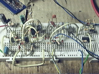
The control circuit itself, it uses an LM393 as a 10Khz 10% duty cycle oscillator and a PWM comparator. There are also five BC550/BC560 transistors [zero-cross comparator, etc..] and a lot of 1N4148 diodes. It also uses a 4N25 optocoupler for remote shutdown. The circuit powers itself from mains due to its low power consumption. There is also a 555 used as a 50Hz oscillator to allow for careful testing before mains applied [anyway, I allways use isolation transformers for testing offline circuits]. Mains power comes through blue/black wires, test 15V power comes through red/green wires, shutdown pulse comes from blue/green wires and thyristor drive goes through grey/yelow wires

This is the thyristor/diode bridge. Black/green wires are AC input and red/black are capacitor output. A simple 6A diode bridge with both AC terminals connected in paralell is used as a 12A dual diode, together with two BT151/650 thyristors
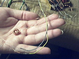
This is the pulse transformer that drives both thyristors. It has a single primary and two secondaries with turn ratios 5:1,1 allowing for proper thyristor triggering and very small current consumption at the same time
I've designed a prototype of phase-sweep soft-start circuit based in two diodes and two thyristors. It's intended for high power offline SMPS applications where 2.000uF or higher capacitances must be charged directly from the mains line. Soft starting in these circumstances is almost mandatory, otherwise peak startup currents in excess of 400A would be generated. It's high enough to trip circuit breakers, blow fuses and even damage diodes and capacitors
The circuit works quite well and uses continuous triggering [10Khz gate pulses] so theoretically it's also suitable for transformer soft-start, replacing thyristors and diodes by a single triac, altough I've not tested this application yet
The bad news are that I don't have drawn full schematics yet, but these are some pictures :
The control circuit itself, it uses an LM393 as a 10Khz 10% duty cycle oscillator and a PWM comparator. There are also five BC550/BC560 transistors [zero-cross comparator, etc..] and a lot of 1N4148 diodes. It also uses a 4N25 optocoupler for remote shutdown. The circuit powers itself from mains due to its low power consumption. There is also a 555 used as a 50Hz oscillator to allow for careful testing before mains applied [anyway, I allways use isolation transformers for testing offline circuits]. Mains power comes through blue/black wires, test 15V power comes through red/green wires, shutdown pulse comes from blue/green wires and thyristor drive goes through grey/yelow wires
This is the thyristor/diode bridge. Black/green wires are AC input and red/black are capacitor output. A simple 6A diode bridge with both AC terminals connected in paralell is used as a 12A dual diode, together with two BT151/650 thyristors
This is the pulse transformer that drives both thyristors. It has a single primary and two secondaries with turn ratios 5:1,1 allowing for proper thyristor triggering and very small current consumption at the same time
quasi said:Hey Zero Cool,
Yep that should work the way you want it.
I would go the fatest Triac you could find though. This torroid of yours is going to pull some juice on switch on.
Will the triac generate any noise ?
Cheers
I dont know if the triacs will generate noise at full on. thats is the question! I may have to use a large relay to bypass the traic once the soft start has ramped up all the way.
I need to build a test setup to test the traics for noise. and if that noise will affect the output of the power supply.
I dont have a spectrum analyzer however. I want to buy a HP3580A but i cant afford one even used right now!
Anyone have any suggestions on how to test for noise? I do have a nice scope. and i could visually check at least but...
Zero
A turned-on triac with continuous gate drive works essentially as two slow soft diodes connected back to back in paralell. It won't produce any RF ringing
Secondary side rectification is the only potential source for RF ringing
PS: Don't try connecting a big toroid transformer to a classic resistive lighting dimmer. The usual problem is asymetric drive to the transformer, causing saturation and a blown triac or no dimming effect at all
Secondary side rectification is the only potential source for RF ringing
PS: Don't try connecting a big toroid transformer to a classic resistive lighting dimmer. The usual problem is asymetric drive to the transformer, causing saturation and a blown triac or no dimming effect at all
Eva said:A turned-on triac with continuous gate drive works essentially as two slow soft diodes connected back to back in paralell. It won't produce any RF ringing
Secondary side rectification is the only potential source for RF ringing
PS: Don't try connecting a big toroid transformer to a classic resistive lighting dimmer. The usual problem is asymetric drive to the transformer, causing saturation and a blown triac or no dimming effect at all
No noise, this is good news!
Eva, please take a look at the kits, i posted a link for. i would not use the kits as-is, only as a basis for designing my own, or maybe as a controller.
As i understand these kits are designed to work with low voltage lighting where a step down transofrmer is normally used.
Please explain more about asymetric drive.
Yes i understand a typical household dimmer doesnt have the Inductor in them needed to handle large highly reactive loads like transformers!
Thats why these kits, looked so interesting to study. surley there is some schematics out there for this sort of thing?
I have a very large variac i use for testing!
Zero
Recommended reading :
SLB0587 datasheet [the kit is based on this IC] :
http://wwww.ges.cz/sheet/s/slb0587.pdf
CONTROL BY A TRIAC FOR AN INDUCTIVE LOAD - HOW TO SELECT A SUITABLE CIRCUIT - Application note from ST :
http://www.st.com/stonline/books/pdf/docs/3566.pdf
I think this should help understanding why lighting dimmers are not suitable to drive inductive loads [SLB0587 shuts down when it detects an inductive load in order to prevent disasters]
Halogen lamp transformers are an exception since they have resistive loads connected to their secondaries and show low magnetizing currents so their primary impedance is resistive [very small phase lag]... Until the lamp fails, the load turns fully inductive and blows both the transformer and the triac
The big inductor is only required for resistive loads in order to limit the dI/dt and thus limit conducted EMI. Inductive loads already contain an inductor by definition
In my soft-start circuit I use the pulse-train method [10Khz] and mains waveform synchronization, both methods are mandatory in order to drive transformers and/or rectified DC loads
I did an extensive search for non dissipative phase-sweep soft-start circuits through google but I found nothing, so I had to design my own

Hi,
i have been using phase controlled inrush current limiter for 3kW PFC front end, but now I use a more elegant solution. This is NTC thermistor especially designed for inrush current limiting made by Epcos. I use B57237S0330M000 which is good for for 4x470uF/450V PFC front end. When PFC starts thermistor is bypassed with relay which is driven by PFC control circuit auxiliray supply voltage. Compared to previous solution startup time is shortened from 10s to 0.5s not counting cost reduction. Only possible drawback of this solution is repetitive cycling of the power switch, which can lead to fuse blowing, since hot thermistor has fairly low resistance.
More information can be found at Epcos web page.
If anyone is still interested in phase controlled approach, I can recommend TDA1085 as a relatively integrated approach.
Best regards,
Jaka Racman
The NTC/relay approach is also very interesting since it gets rid of the usual bulky 50W resistors
The NTC also gets rid of the requirement of the relay to apply fast rise and fall drive transients to the coil since the relay turns on with very little voltage across its contacts and turns off after mains power has been removed, so it makes its control simpler
I evaluated this option but the cost of relays rated at 25Arms or more made me think twice, since a 25A triac is cheaper smaller and maybe easier to drive
Further, in 2..4 KW PFC circuits a 25A or bigger diode bridge with heatsink is required [18..36Arms max. at 160Vrms min.] and adding two cheap 20A thyristors in TO-220 case allows to use both halves of the diode bridge in paralell, allowing also for a smaller diode bridge and for shared dissipation
You may also consider a NTC in paralell with a triac, this gets rid of the relay and the phase control circuit, and 25A triacs usually come in cases with an isolated tab so it can be mounted directly on the case or the main heatsink [remember that any triac used as a switch with inductive loads requires continuous drive like a relay]
But finally, I decided to go for active approach since it allows for very attractive functionality :
- Power good signal to shutdown or activate the load
- Shutdown input to remove power inmediately in case of failure
- Pushbutton on/off switch
- Phase sweep softstart with adjustable startup time
- Line brownout protection to achieve fully retriggerable softstart
- Line undervoltage protection [inherent with power good signal]
- Line overvoltage protection with inmediate shutdown
I decided to try an analog control circuit and evaluate its complexity. Now I'm in doubt because a simple and cheap PIC12C508 microcontroller is able to perform internally most of the logic and timing [even a digital 'period locked loop' to synchronize with mains waveform], requiring only a few external components [zero cross, overvoltage, power good optocoupler, shutdown optocoupler, a transistor to switch the pulse transformer and on/off pushbutton]
That's why I haven't still drawn a full schematic, I may decide to drop the analog approach in favour of a PIC12
The same circuit would be also suitable for transformer startup
PD: Thanks for TDA1085 info
Hi Eva,
as far as I know, in most countries normal wall plug can be rated at max 16A, so 16A Schrack relay is sufficient. It costs 3 Euro in small quantities. 25A requires 2.5mm2 instalation wiring and use of fixed mains connection or use of special industrial IEC connectors, which is something you do not find in most homes.
Otherwise, all you point out is valid, I especially like the PIC idea. In my impementation, I used P104 phase controlled bridge. Instead of transformers, I used phototriac to drive the bridge. I can't remember the actual type used, but it was something like IL4216 . As far as I remember, the reason for using optocouplers instead of transformers was higher sensitivity, since the whole control circuit was supplied by resistor dropping the mains voltage.
Best regards,
Jaka Racman
I use pulse transformer triggering because it allows me to play with turn ratios and scale trigger currents
I apply 35mA pulses to the gate of each thyristor [two units so 70mA total] producing only 1.4mA average current consumption from the 15V supply [derived from mains through 50k resistor and zener diode]. This is accomplished by means of 10% duty cycle 10us pulses [7ma avg.] and 5:1+1 turn ratios on the pulse transformer [1.4ma avg.]
35mA allows to trigger up to 25A TO-220 thyristors like Philips BT145
But my current job is repairing audio equipment, so I'm doing all the 'power conversion' experimentation and development on my own. I noticed some demand for affordable very high current 14.4V semi-industrial power supplies to power car audio and automotive equipment for test and exhibition purposes. I have not much money to expend on industrial type component modules or high sensitivity optocouplers but I have enough patience to wind transformers
The current PFC converter prototype produces 440V 4.6A from 160V to 280V AC and uses only four cheap TO-220 power devices [two SGP10N60 IGBTs and two MUR860 diodes, at 45Khz, the cheaper ones that do the job]. Input inductor is 650uH 20A [E65 core 48T w/2.7mm gap and patience for winding] and output capacitors are 3x330uF 500V. I use a coupled inductor in series with the diodes [it charges during diode recovery and then it dumps its energy to the output] to achieve soft switching [40A/us recovery for each diode/igbt, 80A/us total, and again, patience for winding ]. I've not seen any references to this coupled inductor technique on internet so it may be even an original idea [simple and with no turn-on losses but requires 600V devices for 440V output]
I apply 35mA pulses to the gate of each thyristor [two units so 70mA total] producing only 1.4mA average current consumption from the 15V supply [derived from mains through 50k resistor and zener diode]. This is accomplished by means of 10% duty cycle 10us pulses [7ma avg.] and 5:1+1 turn ratios on the pulse transformer [1.4ma avg.]
35mA allows to trigger up to 25A TO-220 thyristors like Philips BT145
But my current job is repairing audio equipment, so I'm doing all the 'power conversion' experimentation and development on my own. I noticed some demand for affordable very high current 14.4V semi-industrial power supplies to power car audio and automotive equipment for test and exhibition purposes. I have not much money to expend on industrial type component modules or high sensitivity optocouplers but I have enough patience to wind transformers
The current PFC converter prototype produces 440V 4.6A from 160V to 280V AC and uses only four cheap TO-220 power devices [two SGP10N60 IGBTs and two MUR860 diodes, at 45Khz, the cheaper ones that do the job]. Input inductor is 650uH 20A [E65 core 48T w/2.7mm gap and patience for winding
] and output capacitors are 3x330uF 500V. I use a coupled inductor in series with the diodes [it charges during diode recovery and then it dumps its energy to the output] to achieve soft switching [40A/us recovery for each diode/igbt, 80A/us total, and again, patience for winding ]. I've not seen any references to this coupled inductor technique on internet so it may be even an original idea [simple and with no turn-on losses but requires 600V devices for 440V output]Hi Eva,
I am sorry to disappoint you but using flyback as a turn on snubber is rather old. You might have a look at the Fig 10c from slup100.pdf . I first used it in my first high power design (2.5kW buck regulator using bipolars) more than 20 years ago. At those times nondissipative snubbers were a more common thing.
One hint you might want to consider is using iron core for your PFC inductor. With deltaB around 20mT to 30mT iron core losses are quite acceptable. In my experience you could use approx the same size core as ferrite one, that would be SM65 in your case. Another minor issue is mounting thyristors to the main heatsink. I think that would give rise to the common mode intrference by capacitive coupling.
Good luck with your project, I liked your bipolar full bridge very much.
Best regards,
Jaka Racman
- Status
- This old topic is closed. If you want to reopen this topic, contact a moderator using the "Report Post" button.
- Home
- Amplifiers
- Solid State
- Eye of the Beholder!