Sounds sweet. But does this transformer have a 110-0-110 secondary? If so, you will not have a center tap for your +/-65 (actually, it will come out to more like +/-77V at no load). However, having a 5kVA transformer and a huge chassis, you are in luck. You will need to build an artificial floating ground, with 2 resistors in series, the junction of which will be ground. But, these resistors will need to draw as much or more power than the amp itself, making the whole system less than 50% efficient, and dissapating LOTS of heat from the resistors, but I think you can handle that with your monster tranny and big chassis, which I'm sure can house a serious heatsink. They'll need to be huge, maybe you can cut down some heating element from an old oven or something and emerse it in water for cooling (or make an amp/oven combo ). Or, there is a supplier of huge heatsink mount resistors, http://www.riedon.com . Also, why not just wire the pri. for 220 and use a dryer or range outlet? Between the floating ground, regulators and amp, maybe you can just about use up that 5kVA after all .
You can get MG Chemicals photoresist boards and supplies (you will be able to make factory quality boards easily in an hour or so) at Allied Electronics, http://www.alliedelec.com ,and I'm sure elsewhere too. As for a computer program, CircuitMaker/TraxMaker should suit your needs.
Can't wait to see your work!
But does this transformer have a 110-0-110 secondary? If so, you will not have a center tap for your +/-65 (actually, it will come out to more like +/-77V at no load). However, having a 5kVA transformer and a huge chassis, you are in luck. You will need to build an artificial floating ground, with 2 resistors in series, the junction of which will be ground. But, these resistors will need to draw as much or more power than the amp itself, making the whole system less than 50% efficient, and dissapating LOTS of heat from the resistors, but I think you can handle that with your monster tranny and big chassis, which I'm sure can house a serious heatsink. They'll need to be huge, maybe you can cut down some heating element from an old oven or something and emerse it in water for cooling (or make an amp/oven combo ). Or, there is a supplier of huge heatsink mount resistors, http://www.riedon.com . Also, why not just wire the pri. for 220 and use a dryer or range outlet? Between the floating ground, regulators and amp, maybe you can just about use up that 5kVA after all . You can get MG Chemicals photoresist boards and supplies (you will be able to make factory quality boards easily in an hour or so) at Allied Electronics, http://www.alliedelec.com ,and I'm sure elsewhere too. As for a computer program, CircuitMaker/TraxMaker should suit your needs.
Can't wait to see your work!
I recomended Eagle from www.cadsoft.com as a good schematic/PCB layout program a few posts back. It's definitely a program worth checking out.
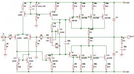
You don't need two sets of LED/R networks for the current sources. Use D1/R1 and connect the base of Q16 to the same point as the base of Q3. Get rid of D2/R8. Also you can bypass the LED with an electrolytic cap to increase stability of the current source.
You should also bypass the Vbe stage with an electrolytic cap (40-100 uF).
If you don't have a center tap on your transformer you can use an output cap like ESP's "El Cheapo". This is cheaper and generates less heat than two enormous resistors.
/Marcus
Will the capacitors have to draw as much power though? It seems to me that wether resistors or capacitors are used on the AC to create an artificial ground, it would be much the same in principal. Capacitors alone on the DC side of the rectifier would not make a good ground right?
I meant a capacitor coupled output of the amp. I think he should use that instead of the artificial earth.
For the artificial earth you are referring to, Kilowatt, you will have to use both resistors and caps. This along with 110 V and several amperes is a pretty bad idea.
/Marcus
For the artificial earth you are referring to, Kilowatt, you will have to use both resistors and caps. This along with 110 V and several amperes is a pretty bad idea.
/Marcus
So the amp won't really have any ground at all. Hmmm, interesting concept (well, I actally have seen that done), but he'd need an output cap. Those have their disadvantages too, like limited performance, limited power output, cost, etc. and they can heat up some too. I guess it's up to Duo.
True, perhaps, but I personally would sacrifice an extra kW for the superior sonic performance the divider would give as opposed to the output cap, if I had the extra power to waste and a way to get rid of the heat. Maybe you wouldn't, and we shall see if Duo would or not, it's his project.
I can't think of any other options, other than a rewind.
Maybe you wouldn't, and we shall see if Duo would or not, it's his project. I can't think of any other options, other than a rewind.
Well, my transformer is made for 110-0-110 out, but I can run it at half voltage and get 55-0-55, so don't worry!
Also, I would sacrifice the energy to use a resistor divider, since I have a pair of 2000w radio loading resistors for dummy loads
But, seems I won't be needing them for this project...
And, I'll get the constant current thing fixed, but when you say Vbe stage, what are you talking about(Q5???) I'm not sure.
Exactly, because, indeed, 110-0-110 essentially means 220 from 110 to 110 doesn't it? And if you can use a transformer for audio interstages(varying voltage), why can't you run a power transformer at half voltage, I must ask!
Also, back to e96mlo::
what exactly do you mean by the Vbe stage?
Also, back to e96mlo::
what exactly do you mean by the Vbe stage?
Duo, you're correct in assuming that it is Q5 I'm talking about. Q5 forms a Vbe multiplication stage along with R18, VR1 and R24.
The resulting bias voltage appears from collector to emitter on Q5 and with your component names the formula is:
Vce = (1 + R18/(VR1+R24))*Vbe
Since this is only for DC bias point, the signal has to make its way through Q5 the best it can and a cap from collector to emitter would help up the signal path.
/Marcus
- Status
- This old topic is closed. If you want to reopen this topic, contact a moderator using the "Report Post" button.
- Home
- Amplifiers
- Solid State
- much less crazy idea