I am looking for a simple cheep amp to make my subwoofer active.
I have designed this very simple amp using darlington transistors such as BDV64 bdv65. but would like to use mosfets instead for a more rugged design.
can any one help?
maybe modify the design to use mosfets instead of bipolar.
I have designed this very simple amp using darlington transistors such as BDV64 bdv65. but would like to use mosfets instead for a more rugged design.
can any one help?
maybe modify the design to use mosfets instead of bipolar.
Attachments
Hi !
Your circuit is a bit too simple, you have no biasing for outputstage
at all. Even if it's "only" for a subwoofer, you can't work without it.
You could try at least 3 diodes between the bases of the bjts.
For mosfets this issue is even bigger, they have a much bigger
threshold for biasing.
Mike
Your circuit is a bit too simple, you have no biasing for outputstage
at all. Even if it's "only" for a subwoofer, you can't work without it.
You could try at least 3 diodes between the bases of the bjts.
For mosfets this issue is even bigger, they have a much bigger
threshold for biasing.
Mike
Simple SW amplifier
How much power are you planning to handle?
What impedance driver do you have in mind (4 - 8 ohms)?
Do you have an actual Subwoofer output available (e.g. DVD player) with channels mixed and filtered down?
As a matter of fact a chip amplifier will probably be actually simpler to build and cheaper to boot!!
Rodolfo
the new schematic
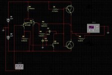
Ok i have corrected the schematic. it works fine in the simulation. the output transistors are actually going to be BDV64 BDV65
but the problem is that i really want to use flat pack transistor and also keep the cost down. so the BDV64/65 are onyl about $4 australian each the whole PCB and components will only cost about $15 austalian thats about $11US.
I am going to biulding this amp this wekend just for fun but if anyone can help with a similar design using mosfet , i will go for that design. because the BDV64/65 do not have a good Safe operating area compared to similar priced mosfets.
Any help would be apreciated as I have never designed or biult a mosfet AMP.
Attachments
Hi !
One more thing: You also should place a 100kohm resistor from
base of input-bjt to ground, and add a inputcapacitor (~4.7uF mks
or 10-22uf electrolytic). Or you might get some strange inputoffset,
depending on the subwoofer-out from preamp.
Did you zoom into crossoverregion ? (In oscilloscope)
Mike
One more thing: You also should place a 100kohm resistor from
base of input-bjt to ground, and add a inputcapacitor (~4.7uF mks
or 10-22uf electrolytic). Or you might get some strange inputoffset,
depending on the subwoofer-out from preamp.
Did you zoom into crossoverregion ? (In oscilloscope)
Mike
Thanks Mike
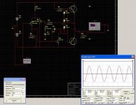
I have added the input resistor and capacitor as you mentioned.
Actually i have just made the PCB, it is ready for drilling I will know how it sounds over the weekend I hope.
here is a picture of the PCB. the transistors mount flat on the bottom of the board so that the board and the transistors mount onto the heatsink easily.
board is very small only about 9cm x 4 cm or less than 4 inch x 2 inch.
if any one is interested i will post more info after a tial run.
I was hoping to get close to 100 w RMS into 8 ohms with mosfets but I will probably only get about 70 w RMS with the darlingtons.
Attachments
Hi david.
Thats some nice transistors you have there. I bought a kit amp using those devices and it sound very good.
The amp i designed doesnt have enough current to drive the mjw21195 devices , but if you added an extra transistor to each of the mjw21194/5 's it would probably work.
i have attached a pdf to explain. but since the mjw21194/5 are quite expensive i would experiment with some cheeper devices, also the sound quality of my amp is only good upto about 1khz.
Attachments
I wish I had the restraint to keep things this simple ")
A couple of thoughts came to mind:
1. The gain of 101 is a little high. You would get peak power at only 300mV input. Try changing R3 to 4.7K.
2. DO NOT use this to drive anything lower than 8 ohms. If you wish to do so, lower the supply voltage or add another pair of output devices in parallel.
A couple of thoughts came to mind:
1. The gain of 101 is a little high. You would get peak power at only 300mV input. Try changing R3 to 4.7K.
2. DO NOT use this to drive anything lower than 8 ohms. If you wish to do so, lower the supply voltage or add another pair of output devices in parallel.
MrTransistorm Thanks, advice taken. I was thinking of reducing the 100k resistor , but your idea of increasing the 1k to 3 or 4k may be better.
Also I have biult the amp and tested it. works well but the 3 diodes give too much biasing current and it goes into thermal runnaway. I have added emitter resistors which i dont like the idea of, but are a must to make the unit reliable.
Any way testing is very promising,
noise levels are excellent, input impedence is good,
on the oscilloscope the wave form looks good, I was not able to complete testing as thermal runaway created quite a spectacular event, hehe. never seen a transistor complain so much.
any way emitter resistors should make it stable.
Any body got advice on how small values I can use, I was thinking 0.22 ohms.
Also any body know of any darlingtons that can carry more current, I will only use this for 8 ohms, but the 4 ohms possibility would be good.
Hi
Just seen your new schematic. Can I suggest a few changes?
The long tail pair are not balanced. Try reducing load R2 to 2k5 nearest = 2k7. Try adding emitter degeneration resistors 68r to 330r. Current available to charge C2 is a bit low even for a bass only amp. Reduce Miller cap by factor of ten to 100pF or try even less. RC time constant on NFB a bit low The suggested change to 4k7 cures this but maybe 2k2 will give you an alternative. Try replacing the bias diodes with a VBE multiplier and include a 500r pot in the BE leg for Iq adjustment.
By the way the integrated transistor in the darlington exagerates the thermal runaway, try a discrete darlington. The DC on the output maybe high (due to imbalanced LTP) and would overheat the darlington with the higher volts drop.
I do not like being negative but these ideas may help.
regards & lets hear the outcome
Andrew T.
Thanks for your input andrew.
I have already biult my second prototype for this amp. I have not connected the cro yet. but have had some listening test on low volume. it is 3 almost 3am here now.Seems to be working alright but im yet too see if it will output a good peak to peak output under load, also Andrew you suggested the miller cap, i will test that,
When i get enough courage (i exagerated it to ensure stability) i will reduce it to 100pf as you suggested after i do some tests, It would be good if i could reduce the miller cap sufficiently to allow this amp to run at full 20khz, by simulation it currently triangulates a sin wave at about 1khz.
Also andrew could you explain to me about the imbalanced long tail pair. what happens if the are imbalanced? do they need to be balanced? before you posted i was actually confused about what value to set for R2, because the lower the value R2 gave some reserve current for the base of Q2 to accomodate variations in HFE for Q2, but on the other hand caused a bigger DC output. What do you suggest, what would be an acceptable DC on the output? currently i get about 22mv with or without load connected.
Thanks for all your help so far, i hope soon we will have a cheap active sub woofer amplifier that everyoverone can biuld.
With all respects to keeping the circuit simple, using current sources would improve the performance tremendoulsly. Replacing R1 with a current source allows the VAS transistor(Q2) to drive just the outputs, not also R1 (Ohms Law)
Current source in differential may help with stability.
Darlington outputs are fine if a high current gain is needed, but should be biased with servo transistor for thermal stability.
Current source in differential may help with stability.
Darlington outputs are fine if a high current gain is needed, but should be biased with servo transistor for thermal stability.
Improved Amp
Here is the schematic with a lot of modifications,
Still had problems with the darlingtons blowing even after the emitter resistors were included, I dont know if it's thermal runaway or the SOA of the darlingtons, the data sheet shows that BDV64/65 has early secondary breakdown.So to reduce thermal runaway i have not used darlington transistor. the new devices do not suffer from secondary breakdown until 70 Volts.
I kind of like the 3 diode bias as it means no pot to set up, probably the last thing simple left on this simple amplifier.lol
I share the diodes D4 and D5 to serve as a dual purpose voltage reference for the 2 current sources. I thought it would be less noise in the input to make it also a constant current source.
Anybody got anything else to add, I will probably hold off making the PCB and prototype for this one for a few days incase i missed anything in the new schematic.
Attachments
Hi spiro
the current in the old tail was (42-.65)/82,000=0.5mA
the current in Q1 is 0.65/4,700=0.14mA, because Q3 forces the voltage across R2 to 0.65v or thereby.
the new tail current is (2*0.7-0.65)/1,000=.75mA
Unbalance causes very high distortion in the LTP and will probably cause thermal instability due to different junction temps in Q1 & Q2. The available gain is very low due to low ltp currents, but this helps reduce open loop gain & thereby stability. Increasing the tail current to anything between 1mA and 6mA will increase gain and reduce noise but you must adjust R2 to draw half the tail current. Once you have the extra gain you can take it away again by adding degeneration resistors to the LTP. Adding a current mirror will double the gain and increase the chances of instability unless you compensate somewhere else.
I guessed that your slew rate might not be very good but I had not realised it was that bad. Better to increase your slew rate by at least 20 times and maybe 50 times then filter the input of the amp to reduce its bandwidth ( any comment anyone?).
regards Andrew T.
You know, the more you ask for any improvments, the more complicated the circuit becomes.
So much for simple eh?
Andrew T has a good idea in putting a current mirror circuit in the LTP.
Just a thought, you could replace D4 & D5 with a Zener diode, 2.4V, or 3V. The forward bias voltage of 1N914 may not be excactly the same. If you construct another channel, the current source bias may be off slightly. Will have to change R3 & R5 though.
I would be reluctant to use diodes to bias the outputs, but it should work. Maybe mount the diodes with the transistors so that they are relatively the same temperature.
If you do use darlington outputs, diodes will not suffice....need servo.
You could also add a small series output inductance, between output and speaker.
Is this what you mean by current mirror?
You guys may be right about the 3 diodes, they say that if you hear some thing from 1 person then it is there opinion, if you hear the same thing from 3 people then it's true. But i am determined to at least Make a the PCB and test it with all these new mods before i go servo.
So i have increase the current in Q7 to about 5mA. increased the current in Q6 to around 10mA. Now when i simulate it it seems to triangulate the output at about 100Khz, the gain bandwidth product must be so high now that the feed back is extending the responce. i left the C1 as 100pF, any suggestions what value for C1, I always thought the bigger C1 then the less chance of oscilation. may be the degredation resistors also need to be added. and suggestions for values?
Any way i never used a current mirror. Is this what you guys ment? added Q4 and Q9
sorry for wasting server space, here is another 12Kb schematic.
Attachments
- Status
- This old topic is closed. If you want to reopen this topic, contact a moderator using the "Report Post" button.
- Home
- Amplifiers
- Solid State
- Simple Amp for active subwoofer