(If this thread belongs in Car Audio or any other forums please move it)
After years of collecting parts and such I finally made the pcb for my SMPS (amp soon to follow). The PSU consists of 28 ntp75n06 fets (75 amp 60v), 4x 9 amp mosfet drivers all controlled by a SG3525.
I know the 3525 isn't the most elegant chip to use to I didn't really want to limit the current
The PSU is switching perfectly (with no feedback it switches at a 46% duty cycle on both side at 56khz), I just have to get the transformer wound correctly.
At the moment its wound at 1:2 for testing. The primary is 5+5 with a single 10 turn secondary beging fed into a half bridge rectifier and then into a cap for measurement. The cap has a resistor of 390R to discharge it.
The problem is the current draw and secondary voltage output in this config. I tried different primaries but with no success. The amp draw starts out at 300-400ma and then climbs to 2.5 amps. The voltage on the secondary starts out at 24v and them climbs to 45-50v.
The torroid I'm using is an op48613tc, specs can be found here if anyone knows how to calculate the required turns
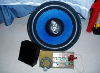
The sub in the pic is 15 inchs and theres a 50c piece for size comparison (it's australian though)
Many Thanks
Matt
After years of collecting parts and such I finally made the pcb for my SMPS (amp soon to follow). The PSU consists of 28 ntp75n06 fets (75 amp 60v), 4x 9 amp mosfet drivers all controlled by a SG3525.
I know the 3525 isn't the most elegant chip to use to I didn't really want to limit the current
The PSU is switching perfectly (with no feedback it switches at a 46% duty cycle on both side at 56khz), I just have to get the transformer wound correctly.
At the moment its wound at 1:2 for testing. The primary is 5+5 with a single 10 turn secondary beging fed into a half bridge rectifier and then into a cap for measurement. The cap has a resistor of 390R to discharge it.
The problem is the current draw and secondary voltage output in this config. I tried different primaries but with no success. The amp draw starts out at 300-400ma and then climbs to 2.5 amps. The voltage on the secondary starts out at 24v and them climbs to 45-50v.
The torroid I'm using is an op48613tc, specs can be found here if anyone knows how to calculate the required turns
The sub in the pic is 15 inchs and theres a 50c piece for size comparison (it's australian though)
Many Thanks
Matt
Attachments
In analog audio, people buy ultra-bulky-oversized transformers, dozens of overrated transistors, big capacitors, huge heatsinks and stuffs everything inside a beautiful case in some fashionable and exotic way. Subjective perception does the rest of the job making it sound wonderful [only to you!!], no matter how much distortion it produces or how much heat it generates
This design/construction method will never work for a SMPS. Any attempt to build a SMPS without a serious scientific mind, experimentation, and proper measuring equipment will result in : Overheating, unexpected currents and voltages, huge EMI production, smoke, etc... [transistors and diodes explode when they fail in >100V applications]
Try something simpler, experiment, measure and learn. Bigger is not better in SMPS [it's only better for the eye]
I would suggest a SG3525 directly driving two banks of two NTP75N06 each, working aroung 40Khz [80Khz clock, experiment with dead time!!], a toroid core much smaller than yours but properly wound [learn about saturation and leakage inductance!!] and a proper EMI-friendly layout. This would be more than enough to power a 500Wrms channel. To power more 500Wrms channels use more 'SMPS cells' with its own transformers, diodes and capacitors. In practice toroid size does not affect power output, it only affects turn counts and practical frequency range
Use the search option to read more about SMPS, that 'unexpected current draw and output pumping' problem has been already discussed several times
Soon I will publish a simple circuit that I designed to help in measuring transformer saturation characteristics, inductor saturation characteristics and leakage inductances [oscilloscope required]
I have already made a small prototype smps before this one. Again, I used the SG3525 as per Rod Elliots non regulated design which produced 35-0-35 very reliably to two p3a amps.
Although I'm no expert at this, I did try to produce an EMI friendly layout based on a few whitepapers and examples in real car amps I have repaired. The board is actually double sided, the side in the picture has the 12v and the connection for the primaries. The bottom layer is a ground plane with some components for the SG3525 I couldn't fit easily on the top layer.
Back to the problem, I rewound the transformers with the correct 13 turns (triple strand of 0.65mm) and wound the secondary with 26 turns of two 0.65mm wires. To get the 13 turns I went through another thread and found the correct formula as you surgested.
I increased the load to about 400mA and there was no longer the 'output pumping' there was before. The voltage is currently at 19.5v at 56kHz and 45% duty cycle. which seems right for now.
I checked different dead times to seem if the current draw lowered any. At 47.5% on time, the PSU drew about 3 amps idle (no secondary load). At 45%, this dropped to 1.8 amps.
Is this a typical figure for the size transformers I'm using?
I'd guess that a larger transformer (especially a torroid) would have a larger leakage inductance and hence a larger idle current draw?
Could this also be due to the fact I haven't yet got a snubber on the primaries? (waiting for components)
Many Thanks
Matt
Unexpected power consumption in these SMPS is allways due to :
1- Magnetizing currents of the transformer [small if turn counts are right]
2- Losses in the snubbers, the diodes and the switches [again small if things are done properly]. Diodes and switches should run cool with no heatsink at minimum load
3- Cross-conduction due to excessive duty cycle or too slow switch turn-off
4- Transformer saturation due to too high duty cycle or too small primary turn count
5- Parasitistic turn-on of one side just when the other side is normally turning on, this happens due to too fast turn-on and too high gate to ground impedance on the turned off side [turn on/off speeds may be changed by placing a resistor in series with a diode in paralell with other resistor]
Snubbers are mandatory on these circuits to reduce EMI and/or chances of output pumping or control circuit disturbance. First use the oscilloscope to find the ringing frequency on each winding, then add a suitable RC network in paralell so that F_ring=1/(R*C) and use the highest value R that provides acceptable dampening. It requires trial an error. Be aware that oscilloscope probe capacitance may alter ringing frequency [10x mode tends to show less input capacitance]
To reduce ringing on the transformer try to reduce the capacitance between windings [this topic has already been discussed in a big car-smps thread]
To reduce leakage inductance try to spread all windings evenly around the core
Output pumping is related to diseases like ringing, excessive leakage inductance [ = bad magnetic coupling between windings], cross-conduction and transformer saturation. Reduce these factors and you'll get no output pumping even with very small loads
check out tis thread , theres allot info on how to wind the core
http://www.diyaudio.com/forums/showthread.php?s=&threadid=30183&highlight=
looking at the pic your windings look too small , u gotta use many wires in paralell for each winding
http://www.diyaudio.com/forums/showthread.php?s=&threadid=30183&highlight=
looking at the pic your windings look too small , u gotta use many wires in paralell for each winding
- Status
- This old topic is closed. If you want to reopen this topic, contact a moderator using the "Report Post" button.