STW34NB20 mosfets - Part II
Dear all,
As promised some more results for the STW34NB20 PowerMESH mosfets.
Supply = 34 volts
Quiescent current = 1.5 amps (for the pair).
Vbias = 5.24 volts
Q1 = 520 mV
Q2 = 628 mV
Test Setup:
HP8903B > SSM2015-Attenuator-OP275-TPA6120 > Sowter 1:5+5 > STW34NB20 > EI120 2:1 OutTx > 8 ohm load > HP8903B
1. Level sweep at 1.000 kHz into 8 ohms (no filter i.e. 200 kHz measurement bandwidth).
Vac-RMS Dist%
======= =====
0.5 0.110
0.6 0.098
0.7 0.093
0.8 0.088
0.9 0.081
1.00 0.073
1.25 0.057
1.50 0.048
1.75 0.043
2.00 0.039
2.50 0.034
3.00 0.033
4.00 0.039
5.00 0.051
6.00 0.068
7.00 0.091
8.00 0.121
9.00 0.158
10.0 0.213
11.0 0.283
12.0 0.352
13.0 0.414
14.0 0.473
15.0 0.551
16.0 0.550
17.0 0.576
18.0 0.618
19.0 0.666
19.75 0.729
20.0 0.858
N.B. Clipping just visable above 19.75 Vac
=====
2. Frequency sweep at 2.0 Vac RMS between 20 Hz to 100 kHz
Hz % Dist
====== ======
20 0.324
25 0.240
30 0.190
35 0.155
40 0.128
45 0.111
50 0.097
60 0.079
70 0.067
80 0.059
90 0.054
100 0.047
125 0.040
150 0.036
175 0.035
200 0.031
250 0.029
300 0.027
400 0.027
500 0.028
600 0.030
700 0.031
800 0.033
900 0.036
1000 0.038
1100 0.040
1200 0.039
1300 0.039
1400 0.040
1500 0.039
1700 0.039
2000 0.038
2500 0.039
3000 0.041
4000 0.048
5000 0.053
7000 0.063
10000 0.072
11000 0.074
12000 0.075
15000 0.079
20000 0.084
25000 0.091
30000 0.107
35000 0.130
40000 0.160
45000 0.196
50000 0.235
60000 0.318
70000 0.380
80000 0.400
90000 0.386
100000 0.352
Amplifier bandwidth -3 dB at 100 kHz
======================
This is exactly the same power amplifier core configuration as the previous test using the 1212 soundcard.
A rather substantial improvement in results.
Best wishes,
Susan.
Hi Pavel,
Yes, when it works it is great.
When it doesn't, one is flumoxed.
The two sets of figures are raw as I have read them from the front display of the HP 8903B.
I am flumoxed.
Best wishes,
Susan.
PMA said:Susan,
this is interesting. We made a comparison between soundcard spectrum analysis and AP2 spectrum analysis, distortions approx. -100dB. The difference between both measurements was about 2 dB.
Pavel
Yes, when it works it is great.
When it doesn't, one is flumoxed.
The two sets of figures are raw as I have read them from the front display of the HP 8903B.
I am flumoxed.
Best wishes,
Susan.
inputtransformer.
I tried several diffrent transformers as inputtr... yesterday.
First i tried a 160 VA toroid with 230 volts primary and 2 * 11 volts secondary and i worked very well. Next i tried a 100 VA E-I transformer 230 volt prim and 18 volt sec and it gave a little lack of bass. Otherwise the both sounded very nice. I used two 2200 ohms resistors as Rterm. I could not hear any big differens compared with my 50 VA toroid i have been using earlier.
Re: inputtransformer.
Hi Circlomanen,
Thanks for the update on your progress.
Were you able to check the top end frequency response of these transformers?
From my experiance I would guess that the 50 VA toroid is getting up to 20 kHz or so.
Best wishes,
Susan.
Hi Circlomanen,
Thanks for the update on your progress.
Circlomanen said:I tried several diffrent transformers as inputtr... yesterday.
First i tried a 160 VA toroid with 230 volts primary and 2 * 11 volts secondary and i worked very well. Next i tried a 100 VA E-I transformer 230 volt prim and 18 volt sec and it gave a little lack of bass. Otherwise the both sounded very nice. I used two 2200 ohms resistors as Rterm. I could not hear any big differens compared with my 50 VA toroid i have been using earlier.
Were you able to check the top end frequency response of these transformers?
From my experiance I would guess that the 50 VA toroid is getting up to 20 kHz or so.
Best wishes,
Susan.
Re: Re: inputtransformer.
Hi Susan,
Why that ?
What about 16VA toroid with 2x 9V with 2x 115V ?
Where did the end ?
Because I want to buy some one and i'try it then.
all the best
- uwe
Hi Susan,
Susan-Parker said:From my experiance I would guess that the 50 VA toroid is getting up to 20 kHz or so.
Best wishes,
Susan.
Why that ?
What about 16VA toroid with 2x 9V with 2x 115V ?
Where did the end ?
Because I want to buy some one and i'try it then.
all the best
- uwe
When I see this not so small distortion, I am asking you, Susan (and guys too ) : do you not listen, that sound have " coloration " ? I recomend to all read commentary about using of coupling transformers on pages of best manufeacturer of microphone preamps : www.mil-media.com ")
When I see this not so small distortion
Big P., do you listen with electrodes directly stick in your brain? this would eplain you fetishism about THD figures. Else may i be allowed to ask if you brilliant czech engineers did invent the zero THD speaker, but did forgett to tell us about it?
IMO those are no THD figures to realy feel fear.
Did you heard speaker with 0.03 % distortion ( by 120 dB pressure ) - I have heard it . It was invented by one brilliant czech ingeneer and is made in Italy with technology used in F 1 ( quality of Italy manufacturer knows very well german pilot M. Schumacher ). This distortion is not zero, but is very near to this value .
. It was invented by one brilliant czech ingeneer and is made in Italy with technology used in F 1 ( quality of Italy manufacturer knows very well german pilot M. Schumacher ). This distortion is not zero, but is very near to this value .thats ok, for you, those F1 people (i doubt they can hear anything - that job must cause hearing loss) and M Schumacher, who has a face that silly, i doubt he even can spell "music".
Most of us other need to listen to real world speakers, and for those real world amps are just fine, as long as they stay somewhat below 1% or so at full output.
Most of us other need to listen to real world speakers, and for those real world amps are just fine, as long as they stay somewhat below 1% or so at full output.
till,
do you know what is the difference between speaker distortion and solid-state distortion (spectra)? And you surely know that the distortions superimpose, there is nothing like masking of amplifier distortion by speaker distortion. And you would probably be tolerant to 1% 2nd harmonic of the speaker and not to 0.1% 9th harmonic of the amplifier.
do you know what is the difference between speaker distortion and solid-state distortion (spectra)? And you surely know that the distortions superimpose, there is nothing like masking of amplifier distortion by speaker distortion. And you would probably be tolerant to 1% 2nd harmonic of the speaker and not to 0.1% 9th harmonic of the amplifier.
I appreciate both efforts. People who aim for the nicest and smoothest sound are as valuable as the ones who try to develop a more refined product in terms of measurements. Most good designers will seek for a compromise of both. But then, we do have plenty of threads to discuss this.
/Hugo
/Hugo
Hugo, nicest and smoothest sound is not on oportunity to refined products, rather on the contrary. All is only about this thing, that some who don't know to make " refined product " still look for excuse, that worse things are good enough. It is normal human behaviour - Ezop was write two thousand years ago about Fox and sour bunch .
.Re: Re: IC Balanced Line Driver Input
Thats what im going to do for a bridged amp progect using INA134 though
The input which is floating, will take a non balanced or balanced signal (or anything in between) and output a differential signal
It will have as good (even better than a single INA) CMRR even with single ended input aswell as with balanced input, dont know if this is relavent but its a very usefull circuit
darkmoebius said:
It's too bad the balanced line receivers I've seen so far(INA134/137, SSM2015) convert the differential single back to single-ended. It would be great to use the Pro Audio approach of a line amplifier at the preamp and receiver in the Zeus in lieu of the input tranformer.
We'd get all the advantages of noise rejection and the ability to drive any length cables with extremely low distortion.
Do you think it would be possible to feed the + and - differential signals to seperate receivers in the INA2137 dual receiver pictured below and still maintain balance?
An externally hosted image should be here but it was not working when we last tested it.
The + input for both receivers would share the common ground line of the differential cable.
Anyway, just a thought.
Thats what im going to do for a bridged amp progect
using INA134 thoughThe input which is floating, will take a non balanced or balanced signal (or anything in between) and output a differential signal
It will have as good (even better than a single INA) CMRR even with single ended input aswell as with balanced input, dont know if this is relavent but its a very usefull circuit
Attachments
Reading trough a fine thread,
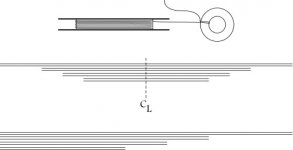
I had to ask for a visual on the windings. I'm asking about setting up the individual wire. Included is a graphic I hope is sent correctly.
Are you using a group of windings all aligned at a starting point, aligned on common center, or threaded in on a ratio? The last option I think was covered in a post about keeping the windings equal and therefore all phase correct. Although I have wondered if layering and then using a separate layer-wound concept would help.
I needed to ask about the windings. Otherwise, I can collect together most of the needed parts list from early posts.
I'm also waiting to hear of compatible preamps. This will be my only hurdle, because I'd like to use an AV unit for the preamp ( a few video inputs, and audio inputs, and control of ), and run these amps for individual channels or on active crossover setups on all channels. If cost begins to be an issue, I will probably plan for a left/right/sub configuration, instead of 5.1 or 6.1.
I, for one, wish there were a more powerful word than congratulations to Susan for the amp design.
Many thanks all,
GH
Attachments
Hey B.Vdos!!!!
The second picture that you posted is exactly what Susan described a few posts ago, but I had a hard time picturing it rom just words. Now, I get it.
I talked to one of the two engineers in charge of the INAxxx products at TI this week and he agreed that this configuration will work perfectly. Actually, he was surpised that TI never introduced a line receiver that is balanced in-balanced out.
I was wondering if using a balanced line receiver before the transformer actually provides better performance than feeding directly into the input transformer. (if extra gain is not needed)
I plan to use ~20 foot interconnects across my living room, so it might be a benefit.
B.VDBOS said:Thats what im going to do for a bridged amp progect
The second picture that you posted is exactly what Susan described a few posts ago, but I had a hard time picturing it rom just words. Now, I get it.
I talked to one of the two engineers in charge of the INAxxx products at TI this week and he agreed that this configuration will work perfectly. Actually, he was surpised that TI never introduced a line receiver that is balanced in-balanced out.
It will have as good (even better than a single INA) CMRR even with single ended input aswell as with balanced input, dont know if this is relavent but its a very usefull circuit
I was wondering if using a balanced line receiver before the transformer actually provides better performance than feeding directly into the input transformer. (if extra gain is not needed)
I plan to use ~20 foot interconnects across my living room, so it might be a benefit.
till said:IMO those are no THD figures to realy feel fear.
Earl Geddes has recently done research that shows that standard THD figures have almost no correlation to how things sound.
http://www.gedlee.com/distortion_perception.htm
dave
- Home
- Amplifiers
- Solid State
- Zero Feedback Impedance Amplifiers