Hi Michael.
Thank you for your question...
I have found that fiddling around with extras doesn't seem to help as it starts getting complicated and swings n' roundabouts kick in.
Matching up a second pair of power devices and the power supply ripple stuff is probably not going to be quite so good. Also it will eat up the power supply headroom, which would then mandate uping the supply volts from circa 35 to 40 plus. Not a problem but then the bias circuit needs a few more components.
However you are most welcome to try and I would be intersted in any sucess, as anything more than a switch and a light bulb is obvioulsy too complicated for an air-head like myself.
If you had a specific circuit configuration in mind, with component values, then I might be able to try it out should I have the time.
I am ordering a set of nice non inductive power resistors so I can get the full power curves as Bear wants to see (pitty there arn't any specs on his triode mosfet amp available - but I am sure it sounds just as good as eva's).
Distortion levels drop BTW as the load impedance increases and even at 16 ohms is very much improved - however that isn't "real world" currents and core fluxes now is it.
I will post as and when I have anything further to add, and update the web pages at some point.
BW,
Susan.
Thank you for your question...
Ultima Thule said:Susan, and all,
I would be curious how would a cascode transistor on top on the FET's work in your amplifier.
This way the non-linear input capacitance wont be so source impedance critical.
Just a curious idea in such a design and how it could work and sound, what do you folks think?
Regards
Michael
I have found that fiddling around with extras doesn't seem to help as it starts getting complicated and swings n' roundabouts kick in.
Matching up a second pair of power devices and the power supply ripple stuff is probably not going to be quite so good. Also it will eat up the power supply headroom, which would then mandate uping the supply volts from circa 35 to 40 plus. Not a problem but then the bias circuit needs a few more components.
However you are most welcome to try and I would be intersted in any sucess, as anything more than a switch and a light bulb is obvioulsy too complicated for an air-head like myself.
If you had a specific circuit configuration in mind, with component values, then I might be able to try it out should I have the time.
I am ordering a set of nice non inductive power resistors so I can get the full power curves as Bear wants to see (pitty there arn't any specs on his triode mosfet amp available - but I am sure it sounds just as good as eva's).
Distortion levels drop BTW as the load impedance increases and even at 16 ohms is very much improved - however that isn't "real world" currents and core fluxes now is it.
I will post as and when I have anything further to add, and update the web pages at some point.
BW,
Susan.
bear said:
Your transformer coupled amp will pass NOTHING substantive at ~500kHz due to the self inductance of the xfmr.
If you used amorphous cores and extreme winding techniques you might find that you can push the ~250kHz limit slightly.
Hi Bear,
This is not true WRT multifilar wound trannies which can have
BW to many MHz due to the high capacitive coupling from
P-S. A good example are the Jensen multifilar line level OP
trannies of which some go 0.15Hz to 15MHz.
I would characterise that as a wide BW transformer
")
At these higher frequencies the core is largely out of the equation.
Cheers,
Terry
Hi Hugo,
I tried phoning but must have just missed them as it was a shave past five o'clock.
You could email them - they should have the details on file.
There is probably some upgrades they can do to the laminations as well but one should ensure that the overall bandwidth isn't crunched too much.
And there is always the option of a nice Mu-metal box - although those are Mu-cho expensive
BW,
Susan.
Netlist said:Susan,
I entered the input transformer # in Sowter’s search engine and got the
"No matching products were found" error.
Maybe the # is obsolete?
Could you please have a look at this?
/Hugo
I tried phoning but must have just missed them as it was a shave past five o'clock.
You could email them - they should have the details on file.
There is probably some upgrades they can do to the laminations as well but one should ensure that the overall bandwidth isn't crunched too much.
And there is always the option of a nice Mu-metal box - although those are Mu-cho expensive
BW,
Susan.
At high frequencies, audio transformers with several multi-layer interleaved windings work as complex resonators where each winding resonates at one or more frequencies due to self leakage inductance and self capacitance and also resonates with other windings due to inductive and capacitive coupling
It's obvious you will get measurable output up to very high frequencies [as Susan has already measured], but most of these high frequencies excite winding resonances and produce lots of peaks and dips in the frequency response and also in the input and output impedance curves of the transformer
In comparison, simpler SMPS transformers with a couple of single layer windings show only one resonance for each winding and a pretty inductive output impedance at frequencies well above it's working conditions [altough self-capacitance and leakage inductance cause 2th order rolloffs]
Finally, transformer cores tend to work at high frequencies as if there were a resistor placed in paralell with each turn of each winding, producing unexpected leakage and core dissipation. This behavior is more critical in iron alloy or iron powder cores, I think
Susan,Susan-Parker said:Hi Hugo,
I tried phoning but must have just missed them as it was a shave past five o'clock.
You could email them - they should have the details on file.
Thank you, grabbing the phone at first request was a bit over the top be nonetheless appreciated.
I'll mail them and post the results.
Thanks
/Hugo
Hi Terry,
You suggest that the multifilar transormer is wideband, but does the standard core not absorb energy above 100kHz, and is this not why ferrite cores were developed ? On the other hand, transformer loss might fortuitously compensate for reducing load current due to loudspeaker driver inductance.
Hi Susan,
I've gone kind of quiet since I saw your figures and 'scope traces.
1.7V @ 4 ohms and 2.7V @ 16 ohms means that most conventional multi-driver cabinets could sound quite different to what the loudspeaker designers intended, especially around crossover frequencies. This output could however sound good with full range drivers which otherwise tend to sound 'forward' with conventional low impedance voltage drive.
Also your distortion figure starts low, increases, and then falls again. Is this due to low output biasing being overcome and currents/flux not varying linearly with input voltage, thus operation is gliding between class-A, then Ab, then aB on a per cycle amplitude basis. And, all of this with varying imbalanced gate capacitance acting upon the input transformer, which will modify the known resonance that Eva outlines.
Distortion might be reduced if the input transformer secondary were more resistively damped but then voltage follower buffered, and the output devices then run in genuine class-A from the low impedance buffer output. This should prevent 600 ohm signal generator (or any source ) waveform from being amplifier modulated as presently occurs due to varying output device/input transformer reactivity.
Hi Prosit (Acenovelty)
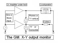
My article has been published in the Nov 2004 Electronics World, and with it my suggested differential method for examining how amplifier output becomes modified by amplifier performance whilst simultaneously dealing with loudspeaker generated back EMFs. See attachment.
This will give a 'live' indication of amplifier linearity with either sinewave or music drive. Just make sure that your 'scope ground is floating and not connected to the line/mains earth.
Why did I not come up with this before ?, for it has illustrated that many 'normal' measurement derived specifications tell us little about how an amplifier distorts when driving a loudspeaker, whether simulated or real-world.
Phones or a tweeter will be quiet, or a dual-beam scope display will be near horizontal to within a few millivolts at 10kHz for a good (class-A) amplifier, but 100s of mV oval with a too reactive output stage, spiky with output stage crossover distortion and all over the place in different ways that are understandable if internal path capacitance/bias/drive currents are overcome when the NFB loop attempts to maintain output voltage irrespectively of dynamically phase shifted loudspeaker current flow.
I have used this arrangement to simulate many designs, and observed weaknesses that designers are not aware arise.
There is much more in the magazine text, including some representative differential error traces, but it really is EW copyright.
Susan, your amplifier does not have NFB, but does it sound 'good' when compared to earlier amplifiers because it does not introduce NFB induced distortion affectations that are avoidable in better designs ?
Cheers for now ............ Graham.
You suggest that the multifilar transormer is wideband, but does the standard core not absorb energy above 100kHz, and is this not why ferrite cores were developed ? On the other hand, transformer loss might fortuitously compensate for reducing load current due to loudspeaker driver inductance.
Hi Susan,
I've gone kind of quiet since I saw your figures and 'scope traces.
1.7V @ 4 ohms and 2.7V @ 16 ohms means that most conventional multi-driver cabinets could sound quite different to what the loudspeaker designers intended, especially around crossover frequencies. This output could however sound good with full range drivers which otherwise tend to sound 'forward' with conventional low impedance voltage drive.
Also your distortion figure starts low, increases, and then falls again. Is this due to low output biasing being overcome and currents/flux not varying linearly with input voltage, thus operation is gliding between class-A, then Ab, then aB on a per cycle amplitude basis. And, all of this with varying imbalanced gate capacitance acting upon the input transformer, which will modify the known resonance that Eva outlines.
Distortion might be reduced if the input transformer secondary were more resistively damped but then voltage follower buffered, and the output devices then run in genuine class-A from the low impedance buffer output. This should prevent 600 ohm signal generator (or any source ) waveform from being amplifier modulated as presently occurs due to varying output device/input transformer reactivity.
Hi Prosit (Acenovelty)
My article has been published in the Nov 2004 Electronics World, and with it my suggested differential method for examining how amplifier output becomes modified by amplifier performance whilst simultaneously dealing with loudspeaker generated back EMFs. See attachment.
This will give a 'live' indication of amplifier linearity with either sinewave or music drive. Just make sure that your 'scope ground is floating and not connected to the line/mains earth.
Why did I not come up with this before ?, for it has illustrated that many 'normal' measurement derived specifications tell us little about how an amplifier distorts when driving a loudspeaker, whether simulated or real-world.
Phones or a tweeter will be quiet, or a dual-beam scope display will be near horizontal to within a few millivolts at 10kHz for a good (class-A) amplifier, but 100s of mV oval with a too reactive output stage, spiky with output stage crossover distortion and all over the place in different ways that are understandable if internal path capacitance/bias/drive currents are overcome when the NFB loop attempts to maintain output voltage irrespectively of dynamically phase shifted loudspeaker current flow.
I have used this arrangement to simulate many designs, and observed weaknesses that designers are not aware arise.
There is much more in the magazine text, including some representative differential error traces, but it really is EW copyright.
Susan, your amplifier does not have NFB, but does it sound 'good' when compared to earlier amplifiers because it does not introduce NFB induced distortion affectations that are avoidable in better designs ?
Cheers for now ............ Graham.
Attachments
Hi Graham !
where can we see/buy your article in "Nov 2004 Electronics World" in Germany ?
I thing it's interesting !
Graham Maynard said:My article has been published in the Nov 2004 Electronics World, and with it my suggested differential method for examining how amplifier output becomes modified by amplifier performance whilst simultaneously dealing with loudspeaker generated back EMFs. See attachment.
This will give a 'live' indication of amplifier linearity with either sinewave or music drive. Just make sure that your 'scope ground is floating and not connected to the line/mains earth.
Why did I not come up with this before ?, for it has illustrated that many 'normal' measurement derived specifications tell us little about how an amplifier distorts when driving a loudspeaker, whether simulated or real-world.
Phones or a tweeter will be quiet, or a dual-beam scope display will be near horizontal to within a few millivolts at 10kHz for a good (class-A) amplifier, but 100s of mV oval with a too reactive output stage, spiky with output stage crossover distortion and all over the place in different ways that are understandable if internal path capacitance/bias/drive currents are overcome when the NFB loop attempts to maintain output voltage irrespectively of dynamically phase shifted loudspeaker current flow.
I have used this arrangement to simulate many designs, and observed weaknesses that designers are not aware arise.
There is much more in the magazine text, including some representative differential error traces, but it really is EW copyright.
Susan, your amplifier does not have NFB, but does it sound 'good' when compared to earlier amplifiers because it does not introduce NFB induced distortion affectations that are avoidable in better designs ?
Cheers for now ............ Graham. [/B]
where can we see/buy your article in "Nov 2004 Electronics World" in Germany ?
I thing it's interesting !
Terry Demol said:
Hi Bear,
This is not true WRT multifilar wound trannies which can have
BW to many MHz due to the high capacitive coupling from
P-S. A good example are the Jensen multifilar line level OP
trannies of which some go 0.15Hz to 15MHz.
I would characterise that as a wide BW transformer
At these higher frequencies the core is largely out of the equation.
Cheers,
Terry
Yeah!!
Wide bandwidth indeed!
I'm quite curious how they achieve this miracle... and it is something of a miracle. I suspect some exotic core material and all the other parameters being highly tweaked and optimized...
also curious about the core size and the power levels that it can work with...
Are you certain it's 15mHz.?? Not 1.5mHz?? (which is still quite good)
_-_-bear
Miracle, oh no it's probably,
"The problem of "complementary coloration" which is " that it is actually impossible to find or create an exact opposite of one "coloration" by employing another. There may be a way to do this in a laboratory test where very specific changes are first made, and then a "reverse" filter applied, but in practice, this is an impossible task to perform - certainly it is wildly improbable ".
Thus quoth the Raven, never more, never more.
Graham's comments dovetail with where I was headed when I asked you to check where your operating points are (I think your wrote ~300ma per device) re: the class of operation...
And Susan, you don't need non-inductive resistors to test at 1kHz! Everything will be quite close enough at 1kHz. for these tests - we don't need several decimal places to determine the general power transfer curve vs. load impedance!
Graham, Your differential test is quite nice... I think that it is similar to a technique that has been around for quite some time. Regardless, it is a very nice way to check the differences between a amp driving a load and a resistor...
Actually, if you used simply a two channel scope with one channel inverted, you'd see the difference signal...
Meethinks one has best to do the first test with identical dummy loads first, since there may be interchannel diffs either due to bias, DC offset and/or outright problems?
Acenovelty, you seem to have kind of an angry but defensive posture in your comments? Dunno why. No one is attacking Susan's idea or design. I surely am not. I am also not suggesting that anyone need subscribe to my personal preferences as far as design or how to set up a system. I am however able to defend and describe these preferences... are you? Also, I am not pushing my preferences on Susan or you.
As far as what my website says I will stand by that.
People as individuals have to decide what they prefer, can accept in terms of compromises (everything is one) as well as what their own "standards" for sound may be. While you may prefer or accept a given system, set of ideas realized as a system, or some given "genre" of sound, that does not mean that either your choice or mine is *definitive* subjectively.
My own designs that I sell commercially are *all compromises* of one sort or another - as I said everything is - but I try to do things that are technically effective and subjectively fine, using the technology to in the main make the choices as far as what compromises are made... and as I said in the end your ears have to decide if that was done well.
Having said that, there are SOME THINGS that can be pointed at from purely an engineering and scientific standpoint that can be shown to be substantial or severe compromises, ones that do not need to be held to be acceptable. So, when we discuss a design on a forum like this, we are talking in the main about the engineering aspect, and only somewhat about the subjective impression of the sonic result... since each of us who actually ends up building the thing in question will then go off and listen to it differently, with different gear and with different standards...
So, the discussion here - for it to move forward in a positive way - about a "new" or "unique" design necessarily needs to revolve around certain aspects of the engineering.
There is *nothing wrong* with you or anyone else building and using Susan's little amp design as-is and enjoying the heck out of it.
Similarly, it is also useful to in the end know all about the factors in the design for two reasons - first you might want to know what is good, what is bad and so know how you might want to adjust or change it, and second - once measured fully you might look at something like the *spectra of distortion* and find that you *like* the effect of something like a non-linear component and *use that* for some purpose or effect here or elsewhere... (I can think of some applications right off the bat)
Bottom line is that understanding brings with it the facility to work with this technology in fun ways - it is not sufficient to dismiss discussions of technology with the suggestion that if it sounds good that is enough. At least that's my take on it.
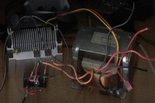
I just built this circuit with some components I had laying around, I used a 230 to 2x 36 volt power transformer at the output, I tested it on my JVC amp and I didn't really notice a change in sound, its probably not perfect but it works.
The fets are IRF511 and for the input I used two 600 ohm audio transformers, the power supply is al 120 VA torodial transformer with a 16 volt 55000 uF capacitor.
I can't turn up the volume high right now to test it, but it does have a distinctive sound, it may sound like a tube amplifier but I never heard one of them so I can't really say.
I took a picture with my scanner.
Attachments
Eva said:At high frequencies, audio transformers with several multi-layer interleaved windings work as complex resonators where each winding resonates at one or more frequencies due to self leakage inductance and self capacitance and also resonates with other windings due to inductive and capacitive coupling
Hi Eva,
This is very true of lesser quality audio transformers but not
necessarily with high quality ones. Really high quality audio
transformers should be characterised with a Bessell rolloff into a
given resistive load. I know that companies such as Jensen
use computer modelling techniques and computer controlled
winding machines so all the RLC parameters can be tightly
controlled and repeated. As such their transformers pass almost
a perfect square wave with absolutely no ringing at all when
driving a specified load.
Having said this, a speaker is far from a perfect resistive
load so there will be some deviation from optimum which is
unavoidable.
Also your comments apply very much to multi filar wound trannies.
They can be very tricky to damp well, especially when they are
very low impedance such as in this case.
Cheers,
Terry
Currently I'm experimenting with high power [2KW to 4KW] active boost PFC converters. These converters are based on an input inductor whose resonances [or absence of them] are very critical since most EMI radiation comes from inductor ringing [I use soft switching so diode recovery is not a problem]
First I wound a bifilar inductor with 3 layers slighty spaced by paper sheets and got awful 16Mhz ringing clearly measurable up to half a meter away from the inductor with the scope and a loop antenna... [What a nice RF transmitter]
Then I wound the same 48 turns in a single layer using thinner wire and radiated ringing almost disapeard [altough excessive RDC caused wire overheating]
I think this proves that all typical multi-layer transformers are prone to excessive ringing and work as antennas at high frequencies mostly due to capacitance between layers, and I think multifilar winding makes things worse
Next I'm planning to test three identical single layer windings stacked on the same former, slighly spaced but perfectly aligned to see if I can keep EMI low while decreasing DCR to a practical value. Obviously DCR is related to resonance damping
First I wound a bifilar inductor with 3 layers slighty spaced by paper sheets and got awful 16Mhz ringing clearly measurable up to half a meter away from the inductor with the scope and a loop antenna... [What a nice RF transmitter
]Then I wound the same 48 turns in a single layer using thinner wire and radiated ringing almost disapeard [altough excessive RDC caused wire overheating]
I think this proves that all typical multi-layer transformers are prone to excessive ringing and work as antennas at high frequencies mostly due to capacitance between layers, and I think multifilar winding makes things worse
Next I'm planning to test three identical single layer windings stacked on the same former, slighly spaced but perfectly aligned to see if I can keep EMI low while decreasing DCR to a practical value. Obviously DCR is related to resonance damping
Hello Bear,
Oh, so sorry, my apologies. I would not presume "to defend and describe these preferences... " to you. As stated earlier, "I'm just a lowly builder" and not an engineer like you at all.
I asked only one question to which you did not deign a reply.
Surely we are all pleased to hear from you that "No one is attacking Susan's idea or design. I surely am not."
My thanks to Graham Maynard whose "article has been published in the Nov 2004 Electronics World" at least gives one a place to look for an answer to my original question posed to you, Bear. Now if we could get Graham to tell us all how to acquire a copy. His attachment whets the appetite for more.
I for one have already placed my call to http://www.thomas-skinner.com/single_phase.htm
about ordering the tranny. Think of it, an amp with what?, only nine parts! Enough scakety yak, I'm more interested in building and listening to "Susan's little amp design as-is" than testing it into the ground. The ears will tell me if it sounds good enough. 
Prosit
Oh, so sorry, my apologies. I would not presume "to defend and describe these preferences... " to you. As stated earlier, "I'm just a lowly builder" and not an engineer like you at all.
I asked only one question to which you did not deign a reply.
Surely we are all pleased to hear from you that "No one is attacking Susan's idea or design. I surely am not."
My thanks to Graham Maynard whose "article has been published in the Nov 2004 Electronics World" at least gives one a place to look for an answer to my original question posed to you, Bear. Now if we could get Graham to tell us all how to acquire a copy. His attachment whets the appetite for more.
I for one have already placed my call to http://www.thomas-skinner.com/single_phase.htm
about ordering the tranny. Think of it, an amp with what?, only nine parts!
Enough scakety yak, I'm more interested in building and listening to "Susan's little amp design as-is" than testing it into the ground. The ears will tell me if it sounds good enough. Prosit
Susan, greeting from Oz again. Not exactly on the topic of amps, but a couple of times in this thread you have mentioned your sensitivity to phase distortion. Is it possible, please, for you to describe the reaction you have? (If the previous objective material has created chaos I hope a subjective comment won't be a complete nightmare.) Thanks Jonathan.
acenovelty said:I for one have already placed my call to http://www.thomas-skinner.com/single_phase.htm
about ordering the tranny.
Hey Ace, what did Skinner have to say? Were you able to get a price quote?
From what Susan posted, the Sowter's should cost about $160 including shipping. If the outputs are under $150 (2), that makes this a fairly affordable amp.
I've got Hammer Dynamics Super-12 97dB/8ohm fullrangers w/ a semi-coaxial supertweeter crossed in at >10kHz. 45-21kHz FR.
This amp could be a nice match if all works out. At least, it would be cool to compare/contrast with the buffered Gainclone I'm collecting parts for.
(BTW, I only have a pair of these, not 4)
An externally hosted image should be here but it was not working when we last tested it.
Sowter
Hi Hugo,
Not a problem, a UK phone call I can manage
Okay, I have just had a nice chat with Brian Sowter.
The 8160 "interstage" transformer is going to be a bit more expensive that when I inquired last a few years ago.
Standard model 8160 with M6 core will be approximately UKP 70 each, plus VAT as appropriate, and shipping.
Discounts:
6 off = 10%
13 off = 15%
25 off = 20%
A M6/Mumetal 50/50% core version will be about 25% more expensive.
Note however that Mumetal saturates at a lower level than M6 (40%?) so a 100% Mumetal core is not advised.
He is also going to give me a quote for the output transformer - split secondary version.
Best wishes,
Susan.
Hi Hugo,
Netlist said:
Susan,
Thank you, grabbing the phone at first request was a bit over the top be nonetheless appreciated.
I'll mail them and post the results.
Thanks
/Hugo
Not a problem, a UK phone call I can manage
Okay, I have just had a nice chat with Brian Sowter.
The 8160 "interstage" transformer is going to be a bit more expensive that when I inquired last a few years ago.
Standard model 8160 with M6 core will be approximately UKP 70 each, plus VAT as appropriate, and shipping.
Discounts:
6 off = 10%
13 off = 15%
25 off = 20%
A M6/Mumetal 50/50% core version will be about 25% more expensive.
Note however that Mumetal saturates at a lower level than M6 (40%?) so a 100% Mumetal core is not advised.
He is also going to give me a quote for the output transformer - split secondary version.
Best wishes,
Susan.
Re: RF mosfets - MRF148s
I have read that logic-level mosfets have a higher transconductance than ordinary ones, so that should make for lower distortion.
Susan-Parker said:The point of the exercise, to show that different mosfet types can have an effect, and that experimentation can produce worthwhile results!
I have read that logic-level mosfets have a higher transconductance than ordinary ones, so that should make for lower distortion.
- Home
- Amplifiers
- Solid State
- Zero Feedback Impedance Amplifiers