Space Charge
Hi,
Whilst space charge may have an effect on low current amplification (particularly for directly heated tubes), for an indirectly heated 6C33C running at almost 300mA on a 37 volts anode supply any effect is going to be way below the noise floor.
What is different is the AC fundamental (at 50/100 or 60/120 Hz) and it's harmonics and the intermodulation effects these have with the music, compared to a steady DC state.
That could well be audible as a difference to the sound and the lack of these intermodulation products could indeed make the sound appear less "alive".
See examples.
Best wishes,
Susan.
P.S. I am not completely convinced that there isn't a degree of thermal modulation "punch through" from the AC heaters, even on the indirectly heated ones. This is an area that I have been intending to look at, but just haven't had the time.
Hi,
I can try with DC but I try to avoid it as I prefer the valve sound with AC heater. With DC heater IMO the the cathode generates a space charge that is polarised and at the end the valve sounds dead. This is just my opinion.
Whilst space charge may have an effect on low current amplification (particularly for directly heated tubes), for an indirectly heated 6C33C running at almost 300mA on a 37 volts anode supply any effect is going to be way below the noise floor.
What is different is the AC fundamental (at 50/100 or 60/120 Hz) and it's harmonics and the intermodulation effects these have with the music, compared to a steady DC state.
That could well be audible as a difference to the sound and the lack of these intermodulation products could indeed make the sound appear less "alive".
See examples.
Best wishes,
Susan.
P.S. I am not completely convinced that there isn't a degree of thermal modulation "punch through" from the AC heaters, even on the indirectly heated ones. This is an area that I have been intending to look at, but just haven't had the time.
Attachments
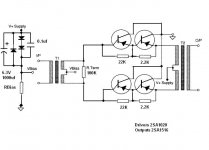
BiPolar Transistor Version
I'm in the process of building a transformer/transistor amp with PNP transistors simply for the reason of being able to ground the collector leads (metal tabs) to the heatsink chassis without insulators, and also for the (hopefully) simple biasing setup.
Regardless of MOSFET or Bipolar or Tubes, I'm wondering about the paths of current flow in the input transformer of the circuit. Where is the return path, the CT or from the other transistor? Could this be modified without CT? Do I need the opposing diode and capacitor to sustain signal flow if the required driving current is higher than what is provided by the biasing network?
Attachments
If you have no noice, hassle with ac-filaments then it's ok and why then using dc... What core material you are using?
@Susan
We discussed in a fewer post of this thread a phono stage using interstage trannies. I have designed one in single ended with IS - trannies in the drain - and LCR-RIAA. Sounds impressive.
The core material is M6
Transformer Laminations
Hi,
From my measurements the line driver and output transformer EI-120 size laminations with the high current low impedance drive of the followers in M6 works well.
For the 3/4" (or thereabouts) sized input and step-up transformers which are higher impedance devices I can see a measurable improvement using MuMetal laminations in the mid-band.
The LF end is not so good with MuMetal at higher levels for the power amp input transformer, but the amounts are still small compared to the loudspeaker distortions down at the LF end.
M6 is still fine to use, but if there is an option to add 50% (or 100% as I do) MuMetal for not too much extra then I would say it's certainly worth considering.
For a 5.1 or 7.1 system I would suggest that the Front Left, Front Right and Front Middle would be the ones to use MuMetal, and the other channels and the bass should be fine with M6.
Best wishes,
Susan.
Hi,
The core material is M6
From my measurements the line driver and output transformer EI-120 size laminations with the high current low impedance drive of the followers in M6 works well.
For the 3/4" (or thereabouts) sized input and step-up transformers which are higher impedance devices I can see a measurable improvement using MuMetal laminations in the mid-band.
The LF end is not so good with MuMetal at higher levels for the power amp input transformer, but the amounts are still small compared to the loudspeaker distortions down at the LF end.
M6 is still fine to use, but if there is an option to add 50% (or 100% as I do) MuMetal for not too much extra then I would say it's certainly worth considering.
For a 5.1 or 7.1 system I would suggest that the Front Left, Front Right and Front Middle would be the ones to use MuMetal, and the other channels and the bass should be fine with M6.
Best wishes,
Susan.
I finished it!!!! It lives, and is loud!!!!
The Bass response is really strong, this thing plays lows with ease and really moves the speaker cone effortlessly. The highs are a bit lacking, but it plays clear, adding bias picked up the highs better some.
It plays loud on only 12V! So far I have no heat at all, it runs really cool.
I finally sourced my input transformers, I found two identical 240V/24V 30VA 50/60 Hz transformers from scrap air conditioners. I run them both in series to have a CT.
I tried using the HV (old primary) winding on the output transformer and noticed lack of frequency response and excessive current draw, so I'm using the speaker directly across the CT winding driven by the transistors. Connected direct gives good frequency response and driving capability.
I'm still tweaking the bias before I settle on a value and stick with it. I will post an updated schematic with all the parts values. I'm still having fun playing with it!!!!
May make a good PA amp for simple use........
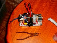
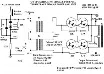
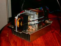
Here it is! Finally a loud and simple 12V amp that does not require an SMPS!
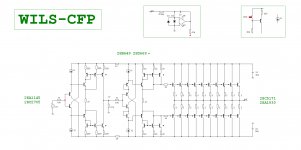
This is the final changes to the circuitry. Feel free to enjoy, copy, modify, or make improvements as needed. Thanks to everyone here @ diyaudio for keeping this discussion going and for the tips required to get it all right!
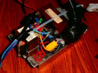
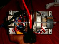
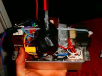
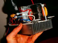
Also uploaded some pics. All PTP, no PCB! As you see, this is a very compact and heavy little amplifier. The output transistors are on the heatsink, concealed by the 3 transformers.
Don't mind the big ball of electric tape with the power wires, it's just covering up my 35V 4700uf Capacitor and Ferrite Toroidal DC filter.
Now about the Amp.............
Bass Response is excellent. Audio on this amplifier even seems bass-boosted.
Treble is good now, I find a trick is to put a 4.7 or 10 ohm resistor in series with input to boost upper highs.
PNP transistors work very good, screwed directly to negative-grounded heatsink with just thermal compound, no insulator required! Devices rated @ 12A, 130W each, genuine Toshiba.
This amp is STRONG! It plays 4 and 2 ohm loads with ease! Amp only gets hot playing 2 ohms, just warm with 4 or 8 ohms. Distortion comes on easy, but sounds good still unless driven to severe clipping.
Amp has High-Gain. Not much needed to get loud!
I have no problem driving asymmetrical loads. I have antiparallel LED's across the speaker output to see them light according to positive or negative swings, and lots of modern audio (esp dubstep) has signals that will drive just one of the LED's for certain notes, but the amp doesn't distort or have any trouble. I still find however, that rock music, or music with heavy guitar or drums sounds best.
Can't wait to try MOSFET on the next one!
This is the final changes to the circuitry. Feel free to enjoy, copy, modify, or make improvements as needed. Thanks to everyone here @ diyaudio for keeping this discussion going and for the tips required to get it all right!
Also uploaded some pics. All PTP, no PCB! As you see, this is a very compact and heavy little amplifier. The output transistors are on the heatsink, concealed by the 3 transformers.
Don't mind the big ball of electric tape with the power wires, it's just covering up my 35V 4700uf Capacitor and Ferrite Toroidal DC filter.
Now about the Amp.............
Bass Response is excellent. Audio on this amplifier even seems bass-boosted.
Treble is good now, I find a trick is to put a 4.7 or 10 ohm resistor in series with input to boost upper highs.
PNP transistors work very good, screwed directly to negative-grounded heatsink with just thermal compound, no insulator required! Devices rated @ 12A, 130W each, genuine Toshiba.
This amp is STRONG! It plays 4 and 2 ohm loads with ease! Amp only gets hot playing 2 ohms, just warm with 4 or 8 ohms. Distortion comes on easy, but sounds good still unless driven to severe clipping.
Amp has High-Gain. Not much needed to get loud!
I have no problem driving asymmetrical loads. I have antiparallel LED's across the speaker output to see them light according to positive or negative swings, and lots of modern audio (esp dubstep) has signals that will drive just one of the LED's for certain notes, but the amp doesn't distort or have any trouble. I still find however, that rock music, or music with heavy guitar or drums sounds best.
Can't wait to try MOSFET on the next one!
Attachments
Last edited:
Hi there ")
Super, great to hear your news.
Thanks for the post and the schematic and pictures.
Best wishes,
Susan.
Here it is! Finally a loud and simple 12V amp that does not require an SMPS! .....
Super, great to hear your news.
Thanks for the post and the schematic and pictures.
Best wishes,
Susan.
but don't let anyone see you carrying that baby around!
+1 I'll be buying the round if you can get it through airport security in your carry on!
Seriously, well done and thanks for the hard work.
Hi Susan and hi to all who read this extraordinary thread.
Firstly I wanted to say congratulations to Susan for such an original design. This is a fascinating topology quite unlike anything I have seen before. I must admit began reading the thread yesterday after searching for the Jean Hiraga design and, a bit like a thriller, I could not stop until I had read all 154 pages.
Secondly I wanted to say bravo for the exceptionally diligent and friendly way you have helped people. You have set and maintained a great good vibe in this thread that has helped many. I wish all threads could be this way.
My interest was piqued because I am looking for amplification for my line source ESL's. I have been running them from 200w Mosfet amps via Amplimo Step-up toroid’s for the past few years. Perfectly adequate but I have wanted to look at a direct drive route for some time. The valve option is an obvious one but the very high voltages involved have put me off. I have neither the skill nor the courage to attempt them. Your amp looks like a very good alternative as it is as direct a s design as I have seen, and that includes some valve direct drives that have capacitors in the signal path.
So I am attracted by the potential to design an output transformer that would match to the ESL's impedance. I note Edwin was a couple of years ahead of me on this thought and I don’t know how he got on but that's the plan for the next few weeks. I am going to build your 75w version first, anyway as it looks delicious, then look at a custom OPT and any PSU beefing that might be needed in order to meet the power demands for the ESL’s.
I note your detailed and helpful guidance on the need for bifilar winding, good core size, tight winding of the coils and the need for extravagate amounts of patience
I have a couple of questions, which I hope you can answer if and when you get the time.
I need a drive voltage of circa 2.0k to 2.5k. This is around half the voltage normally used for a full range ESL but I have a ‘Beverage’ like topology with an active bias so that both stator and diaphragm see the music signal thereby halving the voltage required. Even so, this means assuming a PSU voltage of around 60 volts the OPT would need a ration of circa 1: 42.
This is a simplification and I need to refine that number a little once I have the impedance of the ESL measured. Capacitance is circa 600pf but the diaphragm see’s an additional load due to the air mass which is dominant as I run my SL’s as voltage drive rather than current drive like Edwin, so its difficult to work out.
Does this sort of ratio seem feasible to you?
Another question concerns a trick used to increase the turns ratio seen by the amp by doubling up the OPT’s. The principle being that if you connect the primary’s of two identical OPT’s in parallel and their secondary’s in series you double the turns ratio. From your understanding of your topology does this sound like a feasible options?
If you don’t get a chance to answer don’t worry. I am adept in the flash and bang department and I will feedback my findings for the benefit of others.
One day I’ll tell you about the Dad who thought he killed the cat for Christmas. Luckily he was mistaken.
HV Electrostatic Zeus
Hi Steve,
Thank you for your kind comments.
Yes, in principle there is no reason why one can not drive an electrostatic panel directly.
Sorry for tardiness of reply, only just seen your posts (kindly pointed out to me in fact).
Is that 2.5K RMS or Peak to Peak?
Remember that with a 60 volt supply there will be over 100 volts swing on the primaries. Therefore to get a 2.5KV PP output swing one would need only a 1:25 step up ratio.
Bandwidth is determined by inductance ratios and load capacitance and impedance. The lower the step up voltage, the wider the bandwidth. Also if you don't need such a deep HF extension one can experiment with using a gapped core, varying the gapping which will alter the HF end too.
I have a HV version of my amp (using ETD 59/31/22 ferrite cores) running about 1:30 step up driving a piezzo crystal with a +24 volt supply. It goes seriously over 1000 volts in resonance.
WARNING Standard Tektronix x10 scope probes don't like this. Oops!!!
So yes, these ratios seem feasible.
For this my standard quad-filar topology is not suitable as one will need a multi-section design. I would probably start with 4 primaries and 5 secondaries. My standard EI120 * 2" core size should be okay though.
???
Again my apologies for the delay in replying.
Best seasons wishes,
Susan.
Hi Steve,
Thank you for your kind comments.
My interest was piqued because I am looking for amplification for my line source ESL's. I have been running them from 200w Mosfet amps via Amplimo Step-up toroid’s for the past few years. Perfectly adequate but I have wanted to look at a direct drive route for some time. The valve option is an obvious one but the very high voltages involved have put me off. I have neither the skill nor the courage to attempt them. Your amp looks like a very good alternative as it is as direct a s design as I have seen, and that includes some valve direct drives that have capacitors in the signal path.
So I am attracted by the potential to design an output transformer that would match to the ESL's impedance. I note Edwin was a couple of years ahead of me on this thought and I don’t know how he got on but that's the plan for the next few weeks. I am going to build your 75w version first, anyway as it looks delicious, then look at a custom OPT and any PSU beefing that might be needed in order to meet the power demands for the ESL’s.
I note your detailed and helpful guidance on the need for bifilar winding, good core size, tight winding of the coils and the need for extravagant amounts of patience.
Yes, in principle there is no reason why one can not drive an electrostatic panel directly.
I have a couple of questions, which I hope you can answer if and when you get the time.
Sorry for tardiness of reply, only just seen your posts (kindly pointed out to me in fact).
I need a drive voltage of circa 2.0k to 2.5k. This is around half the voltage normally used for a full range ESL but I have a ‘Beverage’ like topology with an active bias so that both stator and diaphragm see the music signal thereby halving the voltage required. Even so, this means assuming a PSU voltage of around 60 volts the OPT would need a ration of circa 1: 42.
Is that 2.5K RMS or Peak to Peak?
Remember that with a 60 volt supply there will be over 100 volts swing on the primaries. Therefore to get a 2.5KV PP output swing one would need only a 1:25 step up ratio.
This is a simplification and I need to refine that number a little once I have the impedance of the ESL measured. Capacitance is circa 600pf but the diaphragm see’s an additional load due to the air mass which is dominant as I run my SL’s as voltage drive rather than current drive like Edwin, so its difficult to work out.
Bandwidth is determined by inductance ratios and load capacitance and impedance. The lower the step up voltage, the wider the bandwidth. Also if you don't need such a deep HF extension one can experiment with using a gapped core, varying the gapping which will alter the HF end too.
Does this sort of ratio seem feasible to you?
I have a HV version of my amp (using ETD 59/31/22 ferrite cores) running about 1:30 step up driving a piezzo crystal with a +24 volt supply. It goes seriously over 1000 volts in resonance.
WARNING Standard Tektronix x10 scope probes don't like this. Oops!!!
So yes, these ratios seem feasible.
For this my standard quad-filar topology is not suitable as one will need a multi-section design. I would probably start with 4 primaries and 5 secondaries. My standard EI120 * 2" core size should be okay though.
If you don’t get a chance to answer don’t worry. I am adept in the flash and bang department and I will feedback my findings for the benefit of others.
One day I’ll tell you about the Dad who thought he killed the cat for Christmas. Luckily he was mistaken.
???
Again my apologies for the delay in replying.
Best seasons wishes,
Susan.
Here it is! Finally a loud and simple 12V amp that does not require an SMPS!
This is the final changes to the circuitry. Feel free to enjoy, copy, modify, or make improvements as needed. Thanks to everyone here @ diyaudio for keeping this discussion going and for the tips required to get it all right!
Now about the Amp.............
Bass Response is excellent. Audio on this amplifier even seems bass-boosted.
Treble is good now, I find a trick is to put a 4.7 or 10 ohm resistor in series with input to boost upper highs.
PNP transistors work very good, screwed directly to negative-grounded heatsink with just thermal compound, no insulator required! Devices rated @ 12A, 130W each, genuine Toshiba.
This amp is STRONG! It plays 4 and 2 ohm loads with ease! Amp only gets hot playing 2 ohms, just warm with 4 or 8 ohms. Distortion comes on easy, but sounds good still unless driven to severe clipping.
Amp has High-Gain. Not much needed to get loud!
Can't wait to try MOSFET on the next one!
Hi, whats its a T3? primary and secundary voltage?
Great amplifier I'll try whit drive BD139 and output MJ15003. But what relation is output transformer?
Hi Susan,
Please don't be concerned about the delay, I was not expecting you to be around as I stumbled over your thread more or less by accident and was aware that April was the last time you were here. Please thank the kind person who brought my questions to your attention.
Thank you for the answers, very clear and I am delighted that you think that a SUPA amp ( sorry about that, I used to work in branding - there are reasons why I left ) could drive an ESL directly with the right transformer design. I am going to look in more detail into the design and thank you for the guidance on the segmentation. I will use the EI120*2” core size as you recommend.
Over the last few weeks I have been redesigning the ESL to use segmentation so I will be able to use a couple of transformers, one for bass and one for mid to high, which help me to optimize the design of each the transformers.
I will share what I come up with so that others might learn from my mistakes.
The voltage is RMS, not peak to peak, thank you for reminding me that the 60 volt design swings 100 volts peak to peak, I had overlooked that.
The tale of the cat concerns a max volume test on an earlier set of electrostatics. I had waited until the kids and wife were out of harms way and turned up the wick to see if they would arc. Unfortunately I had forgotten about the cat and he decided to investigate. The cat assisted arching test is not recommended, as the cat does not stay in place. He didn’t come home until the New Year
Hi Susan,
1) Can the balaced output of the ES9018 DAC chip (195 ohm differential, 2V RMS) be directly connected to the input of the Zeus amplifier? Or is a voltage gain required?
2) What is the input voltage swing required to get full output power from your Zeus amplifier (using the suggested Sowter input transformer) ?
Thank you for your time.
Best.
Paul
Member
Joined 2009
Paid Member
I think that Susan's amp is a great candidate for driving ESL's.
I have been contemplating such a design for quite some time now.
The thing that most forget or realize in designing a transformer for an ESL is that the primary's inductance needs to be high enough as to not dip down in to the 1 to 2 ohm range for the lowest frequency's of concern.
Having to raise the primary's inductance also raises the overall amount of turns for the secondary.
This also raises the transformers self capacitance as well due to having more turns in general.
In order to help compensate for this one must use a larger core size.
We have many many discussions about this in the Planar's section of this forum.
Here is my latest post to the question what would it take to build a proper transformer for an ESL,
http://www.diyaudio.com/forums/planars-exotics/246137-esl-transformer-question.html#post3771882
The whole thread has lots of great info in it as do a few others as well.
I had mentioned very early in this thread that I think that this design would be great for driving ESL's even with the common power toroid's that we have been using lately.
Except, Because of the transformers design, We are limited to a lowest frequency of about 300-360hz at 40Vrms (113V peak to peak) into a 6v winding.
The higher the primary voltage you use, You must limit your lowest frequency to a higher one or use more primary turns.
This function is linear in transformer design equations.
Here are some impedance measurement charts typical of such a transformer the Antek AN(S)1206,
http://www.diyaudio.com/forums/planars-exotics/161485-step-up-transformer-design-6.html#post3404300
Typically an ESL probably doesn't need more that 2.5KV peak depending on its size.
I have found that 5Kv peak is pretty much the most that any one should consider due to insulation breakdown issues.
And, That they are just plain loud at this level even for my little panel of 3.25" x 9.75" at more than +105db at 1 meter, using a very high bias voltage of at least 7Kv or more.
Getting to 10KV has been proven difficult to do reliably, due to the common materials used.
This includes using a 10Kv peak signal (20Kv p-p).
These voltages were explored solely for testing purpose and are on the very extreme side of things for ESL's but 5Kv to 7kv peak is not uncommon either.
Imagine an increased surface area !!!
I have used much higher voltages and Transformation ratios as high as 1:150 to 1:250 ranges before with my smaller panels where the transformers impedance (self capacitance, and, primary inductance) dominates most of the loads impedance and most of the power (75% to 90%) is dissipated as heat in the transformer itself.
This factor is not so bad for a larger panels, typically 10% (for a very large panel) to 40% power wasted in the transformer.
But can have the similar results for a electrically segmented panel where the capacitance is lower at the highest frequency's and higher at the lowest frequency's.
Don't get me wrong this is actually a good thing, especially for the amplifier.
The simplicity of this design while maintaining a low THD really intrigues me since ESL's are transformer coupled devices anyhow.
I too have been Planning a DD amp for ESL but it is quite an undertaking and almost seems hopeless considering that today's cores are already made of quality material and add very little to the rise of THD above 500hz.
Starting at 1000hz it has been proven difficult to to detect in many of my earlier tests.
Susan's design proves this as well.
Even at 300Hz the edge of saturation at 115v p-p into a 6V winding I have measured less than .2% to .5% THD and this could have been just the amplifier itself as the primary currents are very high at this point.
The links in this post show my results,
http://www.diyaudio.com/forums/planars-exotics/246137-esl-transformer-question.html#post3715632
http://www.esldiy.com/index.php?topic=177.msg322#msg322
The results are typically about .03% THD (-70db) and very well could be just that of my Crown DC300a that I was using to do the tests.
I have found that using more iron helps greatly with low frequency THD even without approaching saturation of the core and staying well below it.
This is also something to consider.
I have finally got some suitable High Current FET's to give this a try and I too will show my results in this thread when I get around to building it.
I have made many variations using a simulator using BJT's and also Opamp's to drive the output devices as well but you can't beat the simplicity of a single driver transformer though.
Cheers !!!
jer
Last edited:
- Home
- Amplifiers
- Solid State
- Zero Feedback Impedance Amplifiers