On Reflection
Thanks Susan for the reply. On reflection afterwards and looking at the transformers on your website, I thought that might be a difficult ask. I suppose a way around it would be to employ a smaller fet (that is one that doesn't draw 500mA) for the line driver?
Thanks Susan for the reply. On reflection afterwards and looking at the transformers on your website, I thought that might be a difficult ask. I suppose a way around it would be to employ a smaller fet (that is one that doesn't draw 500mA) for the line driver?
Line driver bias current and transformer size
Hi,
The line driver is Single Ended, and is a 1:2 step up so mosfet is seeing a 150 ohm load.
I am biasing the mosfet into a linear region of operation (see data sheet):
http://ixdev.ixys.com/DataSheet/DS99192B(IXTH-T20N50D).pdf
To do this I need to use a certain minimum diameter of wire for the current. Once I have decided that, I then decide the number of turns I want for the inductance. Simple maths then gives me the winding window needed. And "just like that" one gets to a EI120 bobbin size!
Also designed to work through a passive crossover to multiple amps for bi-amped speaker drive and to deal with the low end impedance reduction as the frequencies go down to the unit Hz's.
And so yes, could go for smaller drive currents, but distortion would go up and low bass not so good.
Overall I feel that the cost saving would not be significant enough to make any difference in the bigger scheme of things.
YMMV of course")
Best wishes,
Susan.
Hi,
Thanks Susan for the reply. On reflection afterwards and looking at the transformers on your website, I thought that might be a difficult ask. I suppose a way around it would be to employ a smaller fet (that is one that doesn't draw 500mA) for the line driver?
The line driver is Single Ended, and is a 1:2 step up so mosfet is seeing a 150 ohm load.
I am biasing the mosfet into a linear region of operation (see data sheet):
http://ixdev.ixys.com/DataSheet/DS99192B(IXTH-T20N50D).pdf
To do this I need to use a certain minimum diameter of wire for the current. Once I have decided that, I then decide the number of turns I want for the inductance. Simple maths then gives me the winding window needed. And "just like that" one gets to a EI120 bobbin size!
Also designed to work through a passive crossover to multiple amps for bi-amped speaker drive and to deal with the low end impedance reduction as the frequencies go down to the unit Hz's.
And so yes, could go for smaller drive currents, but distortion would go up and low bass not so good.
Overall I feel that the cost saving would not be significant enough to make any difference in the bigger scheme of things.
YMMV of course
Best wishes,
Susan.
Double C-cores & Pre Input Impedance
This is something I am progressing and at the moment it is my intention to move over to using C cores for all the bigger transformers.
For the smaller transformers I will have to do comparative testing between the C cores and standard EI 3/4" Mumetal laminations to make a definitive decision.
I have Rterm1 set to give a nominal 10K input impedance.
This seems okay with the S&B wired for +6dB as I still get the loudspeaker's main driver cones moving back and forth from record warp when playing vinyl, so the low unit Hz frequencies are getting through the system (and that is with six transformers in the audio path - the extra two being in the phono-pre).
Best wishes,
Susan.
Hello Susan
Have you tried out double C-cores as well?
This is something I am progressing and at the moment it is my intention to move over to using C cores for all the bigger transformers.
For the smaller transformers I will have to do comparative testing between the C cores and standard EI 3/4" Mumetal laminations to make a definitive decision.
Another point which I can see is that the input impedance of your line, caused by the ratio of the TVC, is low (I expect you'll use 600 ohm). Any critical problems with source components?
I have Rterm1 set to give a nominal 10K input impedance.
This seems okay with the S&B wired for +6dB as I still get the loudspeaker's main driver cones moving back and forth from record warp when playing vinyl, so the low unit Hz frequencies are getting through the system (and that is with six transformers in the audio path - the extra two being in the phono-pre).
Best wishes,
Susan.
Testing and Matching IXTH20N50D mosfets
Dear All,
I match IXTH20N50D parts using a grounded Gate and a resistor from the source to ground.
In the first instance I use 10 ohms to do a quick sift selection to get the general bins. This doesn't take too long as I am only interested in ball park readings.
I then retest using a 1 ohm part to do the matching.
Normally +24 volt supply to balance between having a representative drop and the power dissipated. I put on the power and then track the voltage drop until the readings more or less stabilise (takes 200 seconds or more per part).
To get "super" matched pairs I then would retest for closest match allowing groups to be on for up to half an hour. However to do this one would need a large quantity of parts to start with and for this I would use the four windings of one of my transformers cores to make sure that the wire resistances are as identical as possible.
N.B. Parts are clamped to a largish aluminium plate to give some thermal mass to work against (they will get overly hot otherwise).
I have at last been able to get a small allocation from the postultimate IXYS manufacturing run (they are doing a special extra one), and I am expecting delivery in August. It took some doing.
So sadly the IXTH20N50D mosfets are now for all intents and purposes obsolete
Best wishes,
Susan.
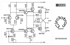
it's a Circlotron with transformer
Stee, really interesting circuit using only local feedback. Have you builded? Is it stable, how is sounds?
So sadly the IXTH20N50D mosfets are now for all intents and purposes obsolete
equivalent/similar replacement, any?
Which depletion MOSFETs are currently produced?
(I can think of DN2540, 10M45, ... is there a list somewhere?)
Matching IXTH20N50D
Thanks Susan for explaining how to match depletion mode mosfets.
I just received 12 pieces with the hope to find a close enough match.
When you will get yours in August I would be happy to send my mosfets to you so chances to find match pairs will probably increase, if you like to do so.
Anyhow IXIS distributor in Australia Braemac informed me that IXTH16N50D2 will be the closest alternative in production.
Dear All,
I match IXTH20N50D parts using a grounded Gate and a resistor from the source to ground.
In the first instance I use 10 ohms to do a quick sift selection to get the general bins. This doesn't take too long as I am only interested in ball park readings.
I then retest using a 1 ohm part to do the matching.
Normally +24 volt supply to balance between having a representative drop and the power dissipated. I put on the power and then track the voltage drop until the readings more or less stabilise (takes 200 seconds or more per part).
To get "super" matched pairs I then would retest for closest match allowing groups to be on for up to half an hour. However to do this one would need a large quantity of parts to start with and for this I would use the four windings of one of my transformers cores to make sure that the wire resistances are as identical as possible.
N.B. Parts are clamped to a largish aluminium plate to give some thermal mass to work against (they will get overly hot otherwise).
I have at last been able to get a small allocation from the postultimate IXYS manufacturing run (they are doing a special extra one), and I am expecting delivery in August. It took some doing.
So sadly the IXTH20N50D mosfets are now for all intents and purposes obsolete
Best wishes,
Susan.
Thanks Susan for explaining how to match depletion mode mosfets.
I just received 12 pieces with the hope to find a close enough match.
When you will get yours in August I would be happy to send my mosfets to you so chances to find match pairs will probably increase, if you like to do so.
Anyhow IXIS distributor in Australia Braemac informed me that IXTH16N50D2 will be the closest alternative in production.
Last edited:
Stee,
Why the link between the collectors of the 2SC3423s..... interesting circuit.
Hugh
not a link, just a smallish dot
Closest alternative depletion mosfets
Hi,
Yes, sure I would be happy to.
Once I have mine I am hoping there will be enough to get sufficient matched pairs to be able to offer some sets out to others. But can't really commit to any numbers yet.
Unfortunately looking at the current curves between the two "closest" isn't close enough, not to do the auto biasing method using the DC resistance of the output transformer windings.
And as soon as one has to have a separate bias supply, the advantages of the depletion mode negative gate voltage turn on are less attractive since one MUST have the negative bias on first before applying the main power, and keep it up after too while the power rail discharges.
In my mind the HUGE attraction of the current parts is the whole auto bias thing, which really makes to overall circuit so minimalist. Once that is gone the whole simplicity of "one can run it of a couple of truck batteries" goes too.
Anyway, this is how things are. Maybe one day I will be able to fab my own parts, but probably not
Best wishes,
Susan.
Hi,
Thanks Susan for explaining how to match depletion mode mosfets.
I just received 12 pieces with the hope to find a close enough match.
When you will get yours in August I would be happy to send my mosfets to you so chances to find match pairs will probably increase, if you like to do so.
Yes, sure I would be happy to.
Once I have mine I am hoping there will be enough to get sufficient matched pairs to be able to offer some sets out to others. But can't really commit to any numbers yet.
Anyhow IXIS distributor in Australia Braemac informed me that IXTH16N50D2 will be the closest alternative in production.
Unfortunately looking at the current curves between the two "closest" isn't close enough, not to do the auto biasing method using the DC resistance of the output transformer windings.
And as soon as one has to have a separate bias supply, the advantages of the depletion mode negative gate voltage turn on are less attractive since one MUST have the negative bias on first before applying the main power, and keep it up after too while the power rail discharges.
In my mind the HUGE attraction of the current parts is the whole auto bias thing, which really makes to overall circuit so minimalist. Once that is gone the whole simplicity of "one can run it of a couple of truck batteries" goes too.
Anyway, this is how things are. Maybe one day I will be able to fab my own parts, but probably not
Best wishes,
Susan.
Hi,
Anyway, this is how things are. Maybe one day I will be able to fab my own parts, but probably not
Best wishes,
Susan.
Setting up a manual fabrication line may be possible using used equipments
and depending on what processes is being used. But since it is an hazardous
process it is still going to be very expensive: Semiconductor device fabrication - Wikipedia, the free encyclopedia
Matching IXTH20N50D
I tested my 12 mosfets today to get an idea which one could be candidate for a pair.
The test I have done as follow:
Gate to ground
Drain to +12VDC
Source in series with 1R to ground
VGS measured: (ordered by voltage and not by testing sequence)
-0.505
-0.655
-0.720
-0.768
-0.801 **b
-0.813 **b
-0.824 *a
-0.825 *a
-0.838 **c
-0.852 **c
-0.888
-0.991
There is only one close match and two so so.
12 parts are probably sufficient to find 1 match pair.
it's always annoying, when suitable parts according to own circuit ideas are discontinued (obsolete) after a short offering time. By transistors (MOSFET and BJT) special suited for audio applications often to observe.Hi,
Yes, sure I would be happy to.
Once I have mine I am hoping there will be enough to get sufficient matched pairs to be able to offer some sets out to others. But can't really commit to any numbers yet.
Unfortunately looking at the current curves between the two "closest" isn't close enough, not to do the auto biasing method using the DC resistance of the output transformer windings.
And as soon as one has to have a separate bias supply, the advantages of the depletion mode negative gate voltage turn on are less attractive since one MUST have the negative bias on first before applying the main power, and keep it up after too while the power rail discharges.
In my mind the HUGE attraction of the current parts is the whole auto bias thing, which really makes to overall circuit so minimalist. Once that is gone the whole simplicity of "one can run it of a couple of truck batteries" goes too.
Anyway, this is how things are. Maybe one day I will be able to fab my own parts, but probably not
Best wishes,
Susan.
I had discover an old description of an old German amplifier brand: Dynacord.
here are three bjt parts in parallel/each half. Naturally there are emitter resistors. But Dynacord uses for each emitter resistor a separate winding part by their special output transformer (six separate winding coils at whole on the primary site). The model was "DEM-286" - go to by post #77 about
http://www.diyaudio.com/forums/soli...odels-quasi-complementary-power-output-8.html
for more informations and several URLs.
This approach could be of interest for you, because then you can use each MOSFET for switching applications, if the value of coil DC resistance is large enough for getting auto bias character. Unfortunately the disadvantage is the more complicated output transformer.
Depletion MOSFET pairs
Hi,
Sorry for the delay in replying, only just seen your posts.
I was at the AES UK conference all weekend (Friday to Monday) as well, so still catching up with my correspondence.
If you are using EI lamination transformers then b and c should be okay to get going with.
There is even a line of thought that says a small imbalance is preferable as it keeps the domains "primed" however I would want to do a bit of specific testing to look at this. A lot of the tube based rule of thumb stuff is not really applicable here as the source impedance and number of turns are so much lower.
If you are using toroids then perhaps not so good, as there is no intrinsic gap unlike where the E and I laminations butt together.
When mine come I can mix and match something better for you.
As to your list, the spread is about 2:1 which is what I would expect from my own experience with a sample group.
Best wishes,
Susan.
Hi,
Sorry for the delay in replying, only just seen your posts.
I was at the AES UK conference all weekend (Friday to Monday) as well, so still catching up with my correspondence.
Hi Susan,
do you think the pair marked as **b are acceptable and would not justify buying another set of mosfets and gambling for another match?
Thanks
If you are using EI lamination transformers then b and c should be okay to get going with.
There is even a line of thought that says a small imbalance is preferable as it keeps the domains "primed" however I would want to do a bit of specific testing to look at this. A lot of the tube based rule of thumb stuff is not really applicable here as the source impedance and number of turns are so much lower.
If you are using toroids then perhaps not so good, as there is no intrinsic gap unlike where the E and I laminations butt together.
When mine come I can mix and match something better for you.
As to your list, the spread is about 2:1 which is what I would expect from my own experience with a sample group.
Best wishes,
Susan.
Parallel mosfets with separate windings
Hi,
Thanks for your post.
The answer here is Litz windings, which I am experimenting with anyway to look at skin effects between 100kHz and 2MHz.
Except rather than use the Litz bundle as a single conductor, one puts one device per individual wire.
I have tried some variations in the past using pairs of devices, the only small issue is the problem than one needs to provide some resistive cross coupling otherwise the whole set takes off and oscillates!
But yes, as long as the combined gate capacitance does not get one, it should be possible.
Best wishes,
Susan.
Hi,
Thanks for your post.
it's always annoying, when suitable parts according to own circuit ideas are discontinued (obsolete) after a short offering time. By transistors (MOSFET and BJT) special suited for audio applications often to observe.
I had discover an old description of an old German amplifier brand: Dynacord.
here are three bjt parts in parallel/each half. Naturally there are emitter resistors. But Dynacord uses for each emitter resistor a separate winding part by their special output transformer (six separate winding coils at whole on the primary site). The model was "DEM-286" - go to by post #77 about
http://www.diyaudio.com/forums/soli...odels-quasi-complementary-power-output-8.html
for more informations and several URLs.
This approach could be of interest for you, because then you can use each MOSFET for switching applications, if the value of coil DC resistance is large enough for getting auto bias character. Unfortunately the disadvantage is the more complicated output transformer.
The answer here is Litz windings, which I am experimenting with anyway to look at skin effects between 100kHz and 2MHz.
Except rather than use the Litz bundle as a single conductor, one puts one device per individual wire.
I have tried some variations in the past using pairs of devices, the only small issue is the problem than one needs to provide some resistive cross coupling otherwise the whole set takes off and oscillates!
But yes, as long as the combined gate capacitance does not get one, it should be possible.
Best wishes,
Susan.
- Home
- Amplifiers
- Solid State
- Zero Feedback Impedance Amplifiers