Re: transformers???
Hi Circlomanen,
Yes, using a pair of same type (and preferably same build batch) you can put the (24 volt?) inputs in parallel and the 230 volt outputs in series.
What you can't do is drive them coupled push-pull as an interstage transformer as the primaries are on separate cores, unless you wire them up so that each arm goes through both transformers.
E.g. 2 off transformers T1a and T1b with windings 12Va + 12Vb on each.
Q1 = (12va) T1a + (12va) T1b
Q2 = (12vb) T1a + (12vb) T1b
This should work.
A quick sketch...

Larger version http://www.susan-parker.co.uk/zeus-2stage-toroid-v1.gif
At the end of the day using specific transformers will give better frequency response and matching and lower distortion. But this will cost a lot more and the toroids seem to be more than adequate to get one going.
N.B. The 15VA toroid that I have has a slightly higher top end frequency response, although it is only a few kilohertz.
I have been working on a maximum of a 1:10+10 step up for my input transformers.
You probably also want to use two matched Rterm's (one for each secondary) rather than just one across the mosfets.
Note: the Rterm values shown in the schematic are nominal, and could be much lower in practice.
My two stage amplifier using the 15VA 12+12:115:115 toroid as the interstage does work from a line level input with a 1:2+2 input transformer and although this small step-up doesn't swing enough to drive much power it does provide a 600 ohm input.
Whereas in the single stage the 15VA toroid is well under 100 ohms input impedance (59 ohms series, 15 ohms parallel) and needs headphone type drive levels.
Hope this helps.
Best wishes,
Susan.
Hi Circlomanen,
Circlomanen said:Hi Susan!
Would it be possible to use 2 30 VA input transformers and connect the 230 volt windings in series to get a midpoint and a greater step up ratio??
Yes, using a pair of same type (and preferably same build batch) you can put the (24 volt?) inputs in parallel and the 230 volt outputs in series.
What you can't do is drive them coupled push-pull as an interstage transformer as the primaries are on separate cores, unless you wire them up so that each arm goes through both transformers.
E.g. 2 off transformers T1a and T1b with windings 12Va + 12Vb on each.
Q1 = (12va) T1a + (12va) T1b
Q2 = (12vb) T1a + (12vb) T1b
This should work.
A quick sketch...
Larger version http://www.susan-parker.co.uk/zeus-2stage-toroid-v1.gif
At the end of the day using specific transformers will give better frequency response and matching and lower distortion. But this will cost a lot more and the toroids seem to be more than adequate to get one going.
N.B. The 15VA toroid that I have has a slightly higher top end frequency response, although it is only a few kilohertz.
I have been working on a maximum of a 1:10+10 step up for my input transformers.
You probably also want to use two matched Rterm's (one for each secondary) rather than just one across the mosfets.
Note: the Rterm values shown in the schematic are nominal, and could be much lower in practice.
My two stage amplifier using the 15VA 12+12:115:115 toroid as the interstage does work from a line level input with a 1:2+2 input transformer and although this small step-up doesn't swing enough to drive much power it does provide a 600 ohm input.
Whereas in the single stage the 15VA toroid is well under 100 ohms input impedance (59 ohms series, 15 ohms parallel) and needs headphone type drive levels.
Hope this helps.
Best wishes,
Susan.
Hi Graham,
Hope you are keeping well.
Thanks")
Not that I am counting you understand but I did "just" happen to notice that we are now number 5 in solid state for both replies and views
Yes, that should work - although for the circuit with the pre-reg protection circuit they would go to the main power rail. The idea of the pre-reg is to be able to turn off the power very quickly - as the current is still rising on the first cycle - so we don't want storage caps at this point.
I probably haven't notice this particular problem as I am using a transformer and when I break the load the winding goes open circuit and thus can't kick current back into the primaries. Or I have just been lucky!
If you mean the 33Rs across the output transformer/inductor primary windings, no not yet although I haven't forgotten. Waiting to do that when I have my testing setup sorted out so I can check distortion effects at the same time.
Work stuff is keeping me distracted at the moment
Best wishes,
Susan.
Hope you are keeping well.
Graham Maynard said:Hi Susan,
What a column !
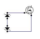
Would reverse biased shunting diodes from each output source to the drain/psu rail prevent possible back EMF induced Mosfet failure ?
Has anyone tried per-half damping resistors yet ?
Cheers ......... Graham.
Thanks
Not that I am counting you understand but I did "just" happen to notice that we are now number 5 in solid state for both replies and views
Yes, that should work - although for the circuit with the pre-reg protection circuit they would go to the main power rail. The idea of the pre-reg is to be able to turn off the power very quickly - as the current is still rising on the first cycle - so we don't want storage caps at this point.
I probably haven't notice this particular problem as I am using a transformer and when I break the load the winding goes open circuit and thus can't kick current back into the primaries. Or I have just been lucky!
If you mean the 33Rs across the output transformer/inductor primary windings, no not yet although I haven't forgotten. Waiting to do that when I have my testing setup sorted out so I can check distortion effects at the same time.
Work stuff is keeping me distracted at the moment
Best wishes,
Susan.
I suspect that your 'special design' keyboards have an auto-reload function build in.Susan-Parker said:Not that I am counting you understand but I did "just" happen to notice that we are now number 5 in solid state for both replies and views
/Hugo
Commentable Experienced Thoughts
Hi BOBO
Back to Back Zeners refers to the configuration which involves connecting 2 zeners in series but with same polarity on connecting middle tag.
This configuration eliminates both negative and positive overdrive of gate voltage.
hope this helps
bobo1on1 said:
Ehm what are back to back zeners? I did put in a 12 volt zener between the gate and the source, that should make sure the Vgs does not exceed 12 volts, or am I wrong?
Hi BOBO
Back to Back Zeners refers to the configuration which involves connecting 2 zeners in series but with same polarity on connecting middle tag.
This configuration eliminates both negative and positive overdrive of gate voltage.
hope this helps
Attachments
.... Hugo, naughty boyNetlist said:
I suspect that your 'special design' keyboards have an auto-reload function build in.
/Hugo

I have the real answer: Susan has chosen two magical trigger words, "zero feedback"!
 This creates interest regardless what's all about. "Class A" is also good
 Not to threadjack again, but....
For those who newbies (like me) who already have RCA or "single-ended" preamps, cd players, etc and still want to try Susan's Zeus amp without a major investment to convert to balanced/differential inputs - digi01 has started an excellent thread based around this single chip design that only uses 2 resistors and capacitors. Total parts cost including the regulators and power supply should be less than $10. The best part is that it may be possible to simply place this tiny SE to Differential converter inside the Zeus amp at it's inputs.
(seems DiyAudio is not displaying pictures right now, so click link)

For those who newbies (like me) who already have RCA or "single-ended" preamps, cd players, etc and still want to try Susan's Zeus amp without a major investment to convert to balanced/differential inputs - digi01 has started an excellent thread based around this single chip design that only uses 2 resistors and capacitors. Total parts cost including the regulators and power supply should be less than $10. The best part is that it may be possible to simply place this tiny SE to Differential converter inside the Zeus amp at it's inputs.
The DRV134 (and DRV135 in SO-8 package) converts a single-ended, ground-referenced input to a floating differential output with +6dB gain (G = 2).
(seems DiyAudio is not displaying pictures right now, so click link)

I can't help thinking that we may be losing the plot a bit resorting to op amps to this drive amp.
Even with my limited experience I have found that finding a an op amp that sounds as good as a good discrete design is not easy.
From the reports so far about this amp I think this amps deserves a better solution.
I can't help thinking that if we have to introduce another perhaps inferia stage to drive this cct, Hugh Dean's idea to have a valve stage instead of the i/p transformers seems increasingly attractive.
Any ideas about a good valve cct for this ?
I don't think it has to be balanced, does it ? The input transformer will do the convertion here I think.
GOOD NEWS I have just discovered that I have have four good sized toroid transformers and on inspection they all seem to have bifilar secondaries...
What do we think about the fact that the primaries are between the secondaries ans the core ?
I also have 16 IRFP044N's - will these be better IRF540's or IRF 530n's ?
mike
Yes, using a pair of same type (and preferably same build batch) you can put the (24 volt?) inputs in parallel and the 230 volt outputs in series.
What you can't do is drive them coupled push-pull as an interstage transformer as the primaries are on separate cores, unless you wire them up so that each arm goes through both transformers.
Thank you Susan. I will try with my 100 VA transformers tonight.This should work.
It can be a fun experment
Hi Mike,
I have talked about using opamps and headphone amps in an effort to keep matters simple.
Two stage amplifer does work quite nicely for those who want to be purists but I have no problem with a descrete design which can be specifically optimised to the task at hand.
Valves should also work.
For a trial of the amplifer we are all in the same boat. Idealy the transformers need to be custom wound and I have asked Plitron for some quotes. Any mains toroid manufacturer could in fact make the output transformer - perhaps Amp-man's friend might be interested?
For the time being these transformers seem to be good enough to demonstrate the amplifiers - which was the original point of the toroids in the first place
Otherwise a conventional EI transformer for the output as they are not dificult to wind oneself. The input one is a diferent matter.
Watch the 55 volts Vdds - fine with power supplies up to 24 volts but not higher.
Could use for the interstage drive of a 2 stage amplifier as this would fit nicely.
I am also looking at the Lundahl parts and he has transformers suitable for input and interstage use.
http://www.lundahl.se/index.html
LL1922 High Level Stepup Line Input Transformer
LL1689 Line Output Transformer looks interesting.
in the news section
http://www.lundahl.se/news.html
both look interesting.
Remember however that these are C section cores and one has to drive primaries across both sections to get proper coupling.
Best wishes,
Susan.
mikelm said:I can't help thinking that we may be losing the plot a bit resorting to op amps to this drive amp.
Even with my limited experience I have found that finding a an op amp that sounds as good as a good discrete design is not easy.
I have talked about using opamps and headphone amps in an effort to keep matters simple.
Two stage amplifer does work quite nicely for those who want to be purists but I have no problem with a descrete design which can be specifically optimised to the task at hand.
From the reports so far about this amp I think this amps deserves a better solution.
I can't help thinking that if we have to introduce another perhaps inferia stage to drive this cct, Hugh Dean's idea to have a valve stage instead of the i/p transformers seems increasingly attractive.
Any ideas about a good valve cct for this ?
I don't think it has to be balanced, does it ? The input transformer will do the convertion here I think.
Valves should also work.
GOOD NEWS I have just discovered that I have have four good sized toroid transformers and on inspection they all seem to have bifilar secondaries...
What do we think about the fact that the primaries are between the secondaries ans the core ?
For a trial of the amplifer we are all in the same boat. Idealy the transformers need to be custom wound and I have asked Plitron for some quotes. Any mains toroid manufacturer could in fact make the output transformer - perhaps Amp-man's friend might be interested?
For the time being these transformers seem to be good enough to demonstrate the amplifiers - which was the original point of the toroids in the first place
Otherwise a conventional EI transformer for the output as they are not dificult to wind oneself. The input one is a diferent matter.
I also have 16 IRFP044N's - will these be better IRF540's or IRF 530n's ?
mike
Watch the 55 volts Vdds - fine with power supplies up to 24 volts but not higher.
Could use for the interstage drive of a 2 stage amplifier as this would fit nicely.
I am also looking at the Lundahl parts and he has transformers suitable for input and interstage use.
http://www.lundahl.se/index.html
LL1922 High Level Stepup Line Input Transformer
LL1689 Line Output Transformer looks interesting.
in the news section
http://www.lundahl.se/news.html
both look interesting.
Remember however that these are C section cores and one has to drive primaries across both sections to get proper coupling.
Best wishes,
Susan.
Re: Commentable Experienced Thoughts
I can't see the point of doing that, with a negative Vgs the mosfet doesn't conduct anyway, and when using only one zener the Vgs can't get below -0.6 volts.
amp_man_1 said:
Hi BOBO
Back to Back Zeners refers to the configuration which involves connecting 2 zeners in series but with same polarity on connecting middle tag.
This configuration eliminates both negative and positive overdrive of gate voltage.
hope this helps
I can't see the point of doing that, with a negative Vgs the mosfet doesn't conduct anyway, and when using only one zener the Vgs can't get below -0.6 volts.
Susan-Parker said:... but I have no problem with a descrete design which can be specifically optimised to the task at hand.
Isn't that what AKSA supplied us with 2 days ago in this post?
You can create an extremely accurate and low distortion diff output from an SE input using a split load emitter follower with a floating power supply.
A conventional emitter follower is set up using an NPN BJT with a supply to the collector, emitter resistor which is split into two equal, series parts, and the negative supply to the bottom of these two resistors. The center of the two series emitter resistors is grounded. The base is biased from a divider string between the positive and negative supply, but the supply is fully floating, which means the winding/frame capacitance should be low.
Output signal is taken capacitively from the emitter and from the negative supply rail. These are exactly and precisely balanced, and both of very low impedance. The circuit, pioneered by a Frenchman whose name escapes me, is eminently suited to tubes as well. The one difficulty is the fully floating supply, but with SS this is not terribly difficult.
Don't ask me how it sounds. I haven't a clue but the idea is extremely elegant and simple.
Cheers,
Hugh
I have no idea what he's talking about, but would appreciate it if someone else could exlpain or make up a schematic.
I just finished doing a measurement on the transformer I intended to use for my input drive, and the results have set me back for a while. I did a scan of the output winding(1/2 of it) on my 18-0-18V toroid intended for input duty, and found that the output inductance was only about 700mH, and that there was a resonance at only a few kHz. The resonance might straighten out a bit with proper output loading, but the low value of input inductance means an impedance of about 90 ohms at 20Hz (not including reflected load impedance). This means I will need a heftier driver than I had earlier envisaged in order to supply the needed magnetizing current at 20Hz.
If I want to spend the money (I probably won't, though), Jensen Transformers seems to have a likely candidate for input transformer, their JT-123-ALCF. This transformer has a decent step-up ratio, and is rated for line output. We use these transformers at work for isolation between a gain-phase analyzer and a power supply under test, to provide some impedance transformation and DC isolation. The frequency response specs are excellent, and from the look of the transformer, they use nickel-iron laminations to get the inductance needed for adequate response at low frequency. They cost about $70 apiece.
I'm going to look at some other toroidal transformers to see if I can find a unit with better inductance. If not, I'll try driving the living daylights out of the units I have...
Hi wrenchone,
Inductance at what frequency?
I can only measure at 120 Hz and 1 kHz.
This is the problem with these toroids as they aren't designed for what we are trying to do with them. To be honest I am more than somewhat surprised that these work at all for the input side of things.
I have found that to get a level frequency response out to the cut off point I have had to load the toroid output (230 or 115+115 volt winding) right down to 3K7. Different transformers will vary (as will ones with only a single 115 volt winding) so a 10K pot across with a sig gen and a scope or meter is preferred to be able to set these up, otherwise the sound will be a bit harsh at the top end.
The toroids therefor need a heftier drive hence my suggestions of using the headphone output or a specific headphone driver chip like that TI thingy.
Also to note that a current feedback device rather than one with voltage feedback is preferred if you want to get those nice flat top square waves on your scope.
Don't bother with the zorbel though, as this only tunes for a given frequency and trashes the rest.
1:3 step up and 66.7:600 ohms impedance and two required per channel. Max output 17 volts but fine for an automotive power level amp or for the input of a two stage amp. Still need that pesky headphone drive though.
The Lundahl's are probably more suitable - but I understand possibly less attractive to people in the USA/Canada as it involves currency exchange, import duty, shipping fees and so forth.
The LL1922 Line Input Transformer can be wired as a 1:4+4 with a 600 ohm input impedance.
http://www.lundahl.se/pdfs/datash/1922.pdf
The LL1689/PP Transformer can be configured as a 1:9+9 or a 1+1:9+9 (or 2:9+9 / 2+2:9+9) however I am uncertain as to the input impedance. Frequency response isn't given either.
http://www.lundahl.se/pdfs/datash/1689.pdf
Then of course there is the Sowter 8160 which was designed specifically for this task and does give a 600/150 ohm input impedance and a 1:10+10 step up. And a bandwidth of several hundred kHz.
http://www.susan-parker.co.uk/zeus-in-tx.htm
Best wishes,
Susan.
wrenchone said:I just finished doing a measurement on the transformer I intended to use for my input drive, and the results have set me back for a while. I did a scan of the output winding(1/2 of it) on my 18-0-18V toroid intended for input duty, and found that the output inductance was only about 700mH, and that there was a resonance at only a few kHz. The resonance might straighten out a bit with proper output loading, but the low value of input inductance means an impedance of about 90 ohms at 20Hz (not including reflected load impedance). This means I will need a heftier driver than I had earlier envisaged in order to supply the needed magnetizing current at 20Hz.
Inductance at what frequency?
I can only measure at 120 Hz and 1 kHz.
This is the problem with these toroids as they aren't designed for what we are trying to do with them. To be honest I am more than somewhat surprised that these work at all for the input side of things.
I have found that to get a level frequency response out to the cut off point I have had to load the toroid output (230 or 115+115 volt winding) right down to 3K7. Different transformers will vary (as will ones with only a single 115 volt winding) so a 10K pot across with a sig gen and a scope or meter is preferred to be able to set these up, otherwise the sound will be a bit harsh at the top end.
The toroids therefor need a heftier drive hence my suggestions of using the headphone output or a specific headphone driver chip like that TI thingy.
Also to note that a current feedback device rather than one with voltage feedback is preferred if you want to get those nice flat top square waves on your scope.
Don't bother with the zorbel though, as this only tunes for a given frequency and trashes the rest.
If I want to spend the money (I probably won't, though), Jensen Transformers seems to have a likely candidate for input transformer, their JT-123-ALCF. This transformer has a decent step-up ratio, and is rated for line output. We use these transformers at work for isolation between a gain-phase analyzer and a power supply under test, to provide some impedance transformation and DC isolation. The frequency response specs are excellent, and from the look of the transformer, they use nickel-iron laminations to get the inductance needed for adequate response at low frequency. They cost about $70 apiece.
1:3 step up and 66.7:600 ohms impedance and two required per channel. Max output 17 volts but fine for an automotive power level amp or for the input of a two stage amp. Still need that pesky headphone drive though.
The Lundahl's are probably more suitable - but I understand possibly less attractive to people in the USA/Canada as it involves currency exchange, import duty, shipping fees and so forth.
The LL1922 Line Input Transformer can be wired as a 1:4+4 with a 600 ohm input impedance.
http://www.lundahl.se/pdfs/datash/1922.pdf
The LL1689/PP Transformer can be configured as a 1:9+9 or a 1+1:9+9 (or 2:9+9 / 2+2:9+9) however I am uncertain as to the input impedance. Frequency response isn't given either.
http://www.lundahl.se/pdfs/datash/1689.pdf
Then of course there is the Sowter 8160 which was designed specifically for this task and does give a 600/150 ohm input impedance and a 1:10+10 step up. And a bandwidth of several hundred kHz.
http://www.susan-parker.co.uk/zeus-in-tx.htm
I'm going to look at some other toroidal transformers to see if I can find a unit with better inductance. If not, I'll try driving the living daylights out of the units I have...
Best wishes,
Susan.
Re: Re: Commentable Experienced Thoughts
Don't forget that when you use a centre-tapped drive transformer one gate has to go negative by the *same amount* the other gate has to go positive. Gate bias offsets things a few volts but at high signal levels it will definitely matter.bobo1on1 said:I can't see the point of doing that, with a negative Vgs the mosfet doesn't conduct anyway, and when using only one zener the Vgs can't get below -0.6 volts.
Re: Re: Re: Commentable Experienced Thoughts
Yes indeed it does, but the transformer/inductor swing of each arm in normal operation means that the gate remains positive to the source at all times - neither mosfet turns off - hence the class A operation.
The zener is there to protect the gate only during abnormal conditions or from overdrive by the input transformer.
BW,
Susan.
Circlotron said:
Don't forget that when you use a centre-tapped drive transformer one gate has to go negative by the *same amount* the other gate has to go positive. Gate bias offsets things a few volts but at high signal levels it will definitely matter.
Yes indeed it does, but the transformer/inductor swing of each arm in normal operation means that the gate remains positive to the source at all times - neither mosfet turns off - hence the class A operation.
The zener is there to protect the gate only during abnormal conditions or from overdrive by the input transformer.
BW,
Susan.
Susan-Parker said:
The Lundahl's are probably more suitable - but I understand possibly less attractive to people in the USA/Canada as it involves currency exchange, import duty, shipping fees and so forth.
Susan,
Lundahl is distributed in the US by Kevin Carter at
http://www.kandkaudio.com/
Best Regards,
Lennart
Hi Lenn,
Thanks for the link, I didn't know that.
Best wishes,
Susan.
Lenn Art said:Susan,
Lundahl is distributed in the US by Kevin Carter at
http://www.kandkaudio.com/
Best Regards,
Lennart
Thanks for the link, I didn't know that.
Best wishes,
Susan.
- Home
- Amplifiers
- Solid State
- Zero Feedback Impedance Amplifiers