Overcoming transformer blues.
All this talk about fancy output transformers and winding techniques and core materials can be swept away in one stroke...
Earlier in this thread I posted a comment http://www.diyaudio.com/forums/showthread.php?postid=488524#post488524
about a conceptually similar topology to the one we are talking about here, but perhaps some of the finer points of it were overlooked.
In Susan's amp cct, as one mosfet source pulls up, the opposite end of the transformer goes down as a result of the coupling of the two halves of the transformer winding. You can connect a loudspeaker to a secondary winding on this transformer, or if the drive capability of the mosfets is sufficient, connect the speaker from source to source, i.e. across the full transformer primary.
In both situations the audio signal has to pass from one winding, through the core and thence to the other winding and then the load. Depending on how good the transformer, the signal wil suffer certain indignities along the way.
In contrast, the topology I spoke about has the advantage that for a given drive polarity, one end of the load is pulled up by a mosfet source while the opposite end is pushed down with an equal "force" by the negative end of the cross-couping capacitor. The point is, provided it doesn't saturate at the lowest frequency and highest level of interest, the quality of the transformer now matters not one bit. It is relieved of the task of transferring audio. You can wind it yourself (as I in fact did) from an old power transformer bobbin and stack and not have to worry about leakage reactance, stray capacitance, horrible quality iron and whatever else. It will give *very* good results.
I see this topology as a natural extension of Susan's.
bobo1on1 said:I just built this circuit with some components I had laying around, I used a 230 to 2x 36 volt power transformer at the output, I tested it on my JVC amp and I didn't really notice a change in sound, its probably not perfect but it works.
The fets are IRF511 and for the input I used two 600 ohm audio transformers, the power supply is al 120 VA torodial transformer with a 16 volt 55000 uF capacitor.
<snip>
Keep in mind that you need to *rewind* the power transformer, per Susan's instructions. Otherwise ur mostly hearing the poor frequency response that the power transformer has!

acenovelty said:Hello Bear,
Oh, so sorry, my apologies. I would not presume "to defend and describe these preferences... " to you. As stated earlier, "I'm just a lowly builder" and not an engineer like you at all.
I asked only one question to which you did not deign a reply.
Surely we are all pleased to hear from you that "No one is attacking Susan's idea or design. I surely am not."
<snip>Enough scakety yak, I'm more interested in building and listening to "Susan's little amp design as-is" than testing it into the ground. The ears will tell me if it sounds good enough.
Prosit
Acenovelty person:
If you had asked a question without the personal attacks, sarcasm and obvious animosity I would have tried to answer it, or passed it along to someone who could.
Based upon your tone of writing and your past posts, I don't think your "apologies" presented here are sincere. Correct me if I am incorrect.
For all I know you think the Bose Wave Radio is all the hi-fi that anyone ever needs - so far be it for me to tell you what to like or dislike, or what to build or not build.
I would suggest that you merely cease to make posts with negative comments, as well as those expressing a nihlist attitude toward anything having to do with measurements and engineering/design. That would be a plan. Give that some serious thought.
_-_-bear
Mumetal laminations
Hi,
A quick note to say that I have ordered a small stack of Mumetal laminations for my input transformer from Sowter.
I will test both 50%/50% mixed M6/Mumetal and 100% Mumetal cores.
The laminations will no doubt take a few days to arrive...
Best wishes,
Susan.
Hi,
A quick note to say that I have ordered a small stack of Mumetal laminations for my input transformer from Sowter.
I will test both 50%/50% mixed M6/Mumetal and 100% Mumetal cores.
The laminations will no doubt take a few days to arrive...
Best wishes,
Susan.
Re: Sowter
Thanks but now Circlotron got me confused.
You know, he ones got the prize of the week for his schematic.
Never mind, you too earned it
These are nice discounts, I will not commit myself but I can see a group buy coming closer.
/Hugo
Susan,Susan-Parker said:Hi Hugo,
Standard model 8160 with M6 core will be approximately UKP 70 each, plus VAT as appropriate, and shipping.
Discounts:
6 off = 10%
13 off = 15%
25 off = 20%
Thanks but now Circlotron got me confused.
You know, he ones got the prize of the week for his schematic.
Never mind, you too earned it
These are nice discounts, I will not commit myself but I can see a group buy coming closer.
/Hugo
bear said:
Keep in mind that you need to *rewind* the power transformer, per Susan's instructions. Otherwise ur mostly hearing the poor frequency response that the power transformer has!
I did notice the response for high frequencies is very bad, it sounded like a low bandwidth AM radio transmission.
So I connected the speakers directly to the fets and the problem was fixed.
However the transformer gets saturated at frequencies below 50 herz (the transformer was made for 50 herz) so the amp starts distorting at certain volume levels, I'm thinking of replacing the transformer with a pair of inductors.
Re: Overcoming transformer blues.
Hi Circlotron,
Thank you for your clarification
... and the more detailed explanation.
I prefer to use secondaries as this allows one to match up against the speaker load, and ensures that in any failure mode - no matter how unlikely (we all make perfect solder joints and never short anything out when probing a circuit after all) full DC cannot be generated across the speaker. One should of course also have a fuse in the supply line - after the smoothing capacitor.
However this is my personal preference, and for higher impedance speakers, i.e. 16 ohms, or headphones the direct connection should work fine.
I do not see it that way, but again this is my personal preference. It is important to use M6 grain orientated steel, not pig iron, but M6 isn't anything special or esoteric as it is a standard (albeit better quality) mains transformer material.
Any measurements for this - distortion versus level and load perhaps.
I of course think my amplifier sounds perfect, but as unlikely as it may be it has been gently pointed out to me that I might just be ever so in error in this supposition
I see capacitors in the audio path, particularly electrolytics, as a "bad thing". Again this is my personal preference based only on my meager 30 years working in electronics. Compared to the thousands of years total experience represented by the viewers of this list that is less than a grain of sand on a beach (chose a beach that you like to complete this analogy).
I did try a circuit configuration with an additional pair of mosfets to produce a constant voltage to the drains of the main mosfets. I used 12 volt zeners plus poly-something caps so that they followed their mosfet keeping a constant voltage on the drain of the mosfet below.
The constant voltage bit worked very well. It is always gratifying when something works first time - rather than going flash-bang and letting out the magic smoke.
And the results?
No real difference at all to the distortion figures - particularly in consideration of taking the measurements on different days.
You could show me the two figures side by side and the only way to distinguish the two is that the headroom of the amp with the additional constant voltage supply mosfets is reduced by four or so volts (unsurprisingly).
I must have got this wrong somehow as I have been told that supplying a constant voltage to the mosfet drains will liniarise them.
Perhaps there is another factor at work here in which the transformer - for all it ills plays - it's part?
Best wishes,
Susan.
Hi Circlotron,
Thank you for your clarification
Circlotron said:All this talk about fancy output transformers and winding techniques and core materials can be swept away in one stroke...
Earlier in this thread I posted a comment http://www.diyaudio.com/forums/showthread.php?postid=488524#post488524
about a conceptually similar topology to the one we are talking about here, but perhaps some of the finer points of it were overlooked.
... and the more detailed explanation.
In Susan's amp cct, as one mosfet source pulls up, the opposite end of the transformer goes down as a result of the coupling of the two halves of the transformer winding. You can connect a loudspeaker to a secondary winding on this transformer, or if the drive capability of the mosfets is sufficient, connect the speaker from source to source, i.e. across the full transformer primary.
I prefer to use secondaries as this allows one to match up against the speaker load, and ensures that in any failure mode - no matter how unlikely (we all make perfect solder joints and never short anything out when probing a circuit after all) full DC cannot be generated across the speaker. One should of course also have a fuse in the supply line - after the smoothing capacitor.
However this is my personal preference, and for higher impedance speakers, i.e. 16 ohms, or headphones the direct connection should work fine.
In both situations the audio signal has to pass from one winding, through the core and thence to the other winding and then the load. Depending on how good the transformer, the signal wil suffer certain indignities along the way.
I do not see it that way, but again this is my personal preference. It is important to use M6 grain orientated steel, not pig iron, but M6 isn't anything special or esoteric as it is a standard (albeit better quality) mains transformer material.
In contrast, the topology I spoke about has the advantage that for a given drive polarity, one end of the load is pulled up by a mosfet source while the opposite end is pushed down with an equal "force" by the negative end of the cross-couping capacitor. The point is, provided it doesn't saturate at the lowest frequency and highest level of interest, the quality of the transformer now matters not one bit. It is relieved of the task of transferring audio. You can wind it yourself (as I in fact did) from an old power transformer bobbin and stack and not have to worry about leakage reactance, stray capacitance, horrible quality iron and whatever else. It will give *very* good results.
Any measurements for this - distortion versus level and load perhaps.
I of course think my amplifier sounds perfect, but as unlikely as it may be it has been gently pointed out to me that I might just be ever so in error in this supposition
I see this topology as a natural extension of Susan's.
I see capacitors in the audio path, particularly electrolytics, as a "bad thing". Again this is my personal preference based only on my meager 30 years working in electronics. Compared to the thousands of years total experience represented by the viewers of this list that is less than a grain of sand on a beach (chose a beach that you like to complete this analogy).
I did try a circuit configuration with an additional pair of mosfets to produce a constant voltage to the drains of the main mosfets. I used 12 volt zeners plus poly-something caps so that they followed their mosfet keeping a constant voltage on the drain of the mosfet below.
The constant voltage bit worked very well. It is always gratifying when something works first time - rather than going flash-bang and letting out the magic smoke.
And the results?
No real difference at all to the distortion figures - particularly in consideration of taking the measurements on different days.
You could show me the two figures side by side and the only way to distinguish the two is that the headroom of the amp with the additional constant voltage supply mosfets is reduced by four or so volts (unsurprisingly).
I must have got this wrong somehow as I have been told that supplying a constant voltage to the mosfet drains will liniarise them.
Perhaps there is another factor at work here in which the transformer - for all it ills plays - it's part?
Best wishes,
Susan.
Hi bobo1on1,
Very pleasing to hear of your progress and that you have something running on the bench.
Yes, the coupling won't be very good at higher frequencies between the primaries and secondaries on a mains transformer.
Valve output transformers are wound in multiple and overlapped sections to get the bandwidth.
Excellent
The circuit won't work with two separate inductors, as the two primary windings work together to generate the negative half of the cycle.
You can strip down the transformer and wind two primaries together (bifilar) which will do the trick. If you can't get the laminations apart because of varnish then it should be possible to bifilar wind by threading - although it will be a bit tedious. Plenty of tape on the bare edges of the laminations to prevent the enamel of the wire being scraped.
Calculate the wire diameter to give you a full bobbin (allowing for the fact that one can't get a 100% fill hand winding - probably 80% by calculation) for about 150 turns.
For every watt one needs about 4 times the VA rating of the transformer to get 25 Hz performance, but for a test bench trial this should not be quite so much of an issue although from the picture you posted it looks quite substantial.
However...
You used two 600 ohm audio transformers, which is an excellent way to get started.
For the less than 50 Hz performance these might be be limiting factor as small mic and line transformers will not have the headroom to generate the relatively high voltage swings.
Might be worth checking that this isn't the limiting factor?
Anyway, very pleasing.
Best wishes,
Susan.
Very pleasing to hear of your progress and that you have something running on the bench.
bobo1on1 said:
I did notice the response for high frequencies is very bad, it sounded like a low bandwidth AM radio transmission.
Yes, the coupling won't be very good at higher frequencies between the primaries and secondaries on a mains transformer.
Valve output transformers are wound in multiple and overlapped sections to get the bandwidth.
So I connected the speakers directly to the fets and the problem was fixed.
Excellent
However the transformer gets saturated at frequencies below 50 herz (the transformer was made for 50 herz) so the amp starts distorting at certain volume levels, I'm thinking of replacing the transformer with a pair of inductors.
The circuit won't work with two separate inductors, as the two primary windings work together to generate the negative half of the cycle.
You can strip down the transformer and wind two primaries together (bifilar) which will do the trick. If you can't get the laminations apart because of varnish then it should be possible to bifilar wind by threading - although it will be a bit tedious. Plenty of tape on the bare edges of the laminations to prevent the enamel of the wire being scraped.
Calculate the wire diameter to give you a full bobbin (allowing for the fact that one can't get a 100% fill hand winding - probably 80% by calculation) for about 150 turns.
For every watt one needs about 4 times the VA rating of the transformer to get 25 Hz performance, but for a test bench trial this should not be quite so much of an issue although from the picture you posted it looks quite substantial.
However...
You used two 600 ohm audio transformers, which is an excellent way to get started.
For the less than 50 Hz performance these might be be limiting factor as small mic and line transformers will not have the headroom to generate the relatively high voltage swings.
Might be worth checking that this isn't the limiting factor?
Anyway, very pleasing.
Best wishes,
Susan.
Hi Graham,
I can recommend the article - all 11-1/2 pages (note that it is part 6).
There is also an article on simulating power mosfets by Cyril Bateman, which makes an interesting counterpoint.
Best wishes,
Susan.
Graham Maynard said:Hi All,
The posts are still piling in.
It should be possible to order a single copy with credit card via
UK 01353 654 431. Cover price is £3.25.
Cheers ............ Graham.
I can recommend the article - all 11-1/2 pages (note that it is part 6).
There is also an article on simulating power mosfets by Cyril Bateman, which makes an interesting counterpoint.
Best wishes,
Susan.
darkmoebius,
Ed Richardson at http://www.thomas-skinner.com/single_phase.htm
has been out of town, but his secretary promised a return call.
Susan's little amp design as-is very likely will run my under construction 7' line arrays just fine.
Then the son can get his hands on my SAE 2401L amp and the Polk SDA 2 speakers he's been lusting for. He will have to pry from the steel grip of my cold dead hands the Lexicon MC4 and the Leach Superamps though. I'm sure he knows how to properly spell nihilist, so he's probably smart enough to build Susan's amp for the rest of his 6.1 surround system we're also working on.
I guess running the line array with an active crossover means I get to build four of her sweet little amps. Without her post I might have bought into a symphony amplifier or some single ended mosfet amp. 
Prosit
Ed Richardson at http://www.thomas-skinner.com/single_phase.htm
has been out of town, but his secretary promised a return call.
Susan's little amp design as-is very likely will run my under construction 7' line arrays just fine.
Then the son can get his hands on my SAE 2401L amp and the Polk SDA 2 speakers he's been lusting for. He will have to pry from the steel grip of my cold dead hands the Lexicon MC4 and the Leach Superamps though. I'm sure he knows how to properly spell nihilist, so he's probably smart enough to build Susan's amp for the rest of his 6.1 surround system we're also working on.
I guess running the line array with an active crossover means I get to build four of her sweet little amps.
Without her post I might have bought into a symphony amplifier or some single ended mosfet amp. Prosit
acenovelty said:darkmoebius,
Ed Richardson at http://www.thomas-skinner.com/single_phase.htm
has been out of town, but his secretary promised a return call.
Cool, let us know when you get the info.
Susan's little amp design as-is very likely will run my under construction 7' line arrays just fine.
Same for my Super-12's. Match made in heaven? We'll have to wait and see.
He will have to pry from the steel grip of my cold dead hands the Lexicon MC4 and the Leach Superamps though.
You've got to love your kids, but that doesn't mean you have to give them all your toys
BTW, I just noticed that you are in the Bay Area. I'm in Los Angeles, but get up there for work and to visit my brother and his family fairly often. I'd love to drop in for listen when you get it all fine-tuned.
Like this?bobo1on1 said:
So I connected the speakers directly to the fets and the problem was fixed.
I tried to get rid of the output transformer (same setup as in the picture) but then the mosfets don't turn on because there is no reference to ground. So I didn't omit it but put the speaker across the primary.
I also tried to connect two loads (voice coils) in series between the mosfets with the ground in between the loads.
Would that work in practice?
From the sim all I got is very distorted figures because transformer models are probably completely wrong.
/Hugo
Attachments
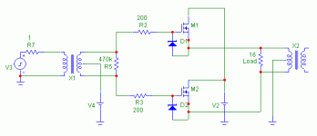
Hi Hugo,
Nice drawing.
That will work, but see my previous post about impedance matching.
No.
But would probably let the magic smoke out of the speakers.
The two primaries HAVE to be magnetically coupled on the same piece of iron.
I have had a singular lack of sucess in my simulation efforts as I have been unable to come up with, or find, a working transformer model.
Mosfet's don't seem to work very well either.
Best wishes,
Susan.
Netlist said:
Like this?
I tried to get rid of the output transformer (same setup as in the picture) but then the mosfets don't turn on because there is no reference to ground. So I didn't omit it but put the speaker across the primary.
Nice drawing.
That will work, but see my previous post about impedance matching.
I also tried to connect two loads (voice coils) in series between the mosfets with the ground in between the loads.
Would that work in practice?
No.
But would probably let the magic smoke out of the speakers.
The two primaries HAVE to be magnetically coupled on the same piece of iron.
From the sim all I got is very distorted figures because transformer models are probably completely wrong.
/Hugo
I have had a singular lack of sucess in my simulation efforts as I have been unable to come up with, or find, a working transformer model.
Mosfet's don't seem to work very well either.
Best wishes,
Susan.
Netlist :
Dual voice coil speakers show different Thiele-Small parameters when voice coils are driven in paralell, in series or when only one of the voice coils is driven
To drive a voice coil means to cause a current to flow across that winding
Also some speakers are not suitable for driving a single voice coil [ie: imagine a center tapped single layer coil, it would require full drive to mantain some BL consistence when voice coil moves in the air gap]
Anyway, in suitable designs [with one or more full layers for each coil] the result is reduced efficiency [-6dB/W] and worse damping of mechanical resonance [higher Qts]
So driving only one voice coil is not recommended
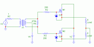
You still need the transformer, but you don't have to use the secondary winding, it solves alot of problems with the inductance of the secondary winding and stuff like that, it's also alot easier to wind yourself.
Susan: I connected two more audio transformers, the primary windings in parallel and the secondary windings in series to double the voltage, the amp still distorts at low frequencies but at a slightly higher volume level.
I found out that the distortion sort of shifts up to a higher level when I increase the bias voltage, so there is a good chance the audio transformers are getting saturated.
I am going to rewind the output transformer, but someone thought it was a good idea to weld the laminations together so I can't get them apart.
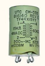
Do you think think two of these audio transformers wil do the job? the specs are: 15Kohm-60Kohm,200c-1kc size:23-36 mm,audio level:+10dbM.
Does anyone know what kind of value c is?
I've also included a picture.
Susan: I connected two more audio transformers, the primary windings in parallel and the secondary windings in series to double the voltage, the amp still distorts at low frequencies but at a slightly higher volume level.
I found out that the distortion sort of shifts up to a higher level when I increase the bias voltage, so there is a good chance the audio transformers are getting saturated.
I am going to rewind the output transformer, but someone thought it was a good idea to weld the laminations together so I can't get them apart.
Do you think think two of these audio transformers wil do the job? the specs are: 15Kohm-60Kohm,200c-1kc size:23-36 mm,audio level:+10dbM.
Does anyone know what kind of value c is?
I've also included a picture.
Attachments
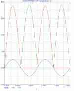
Without transformer:
With a 1kHz sinewave the blue line is the input sinewave,
The red and green are the mosfet sources.
So this is clearly a no-no.
However, the differential offset is only a few millivolts.
See you all tomorrow and thanks for the nice evening
/Hugo
With a 1kHz sinewave the blue line is the input sinewave,
The red and green are the mosfet sources.
So this is clearly a no-no.
However, the differential offset is only a few millivolts.
See you all tomorrow and thanks for the nice evening
/Hugo
Attachments
- Home
- Amplifiers
- Solid State
- Zero Feedback Impedance Amplifiers