Hi Everyone.
Skip to the third last paragraph if you just want to read the question")
Today I decided to start playing with my amp again, after a quite a break. I saw a post the other day by Nelson Pass about using a rectifier bridge to isolate signal ground from Mains ground, and decided to give it a go.
I did this, but didn’t really notice any difference in the noise levels. I decided I should crank it, and to my horror the left channel started distorting very badly. I put every thing back the way it was and the problem was still there I hadn’t cranked the amp up for a while so I don’t know when the problem started.
After many tests (swapping speakers, swapping inputs, driving one channel only at a time, etc) I found that the problem is definitely in the amp, and not the speakers, or the source.
If I drive the amp with the right channel speaker disconnected, the left channel doesn’t distort.
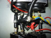
I figured maybe I had a Power Supply problem, even though the PS doesn’t have separate caps for each channel (just 16,000uF per rail +- 63V). I resoldered all of the leads for the left channel, no difference. I unsoldered the left channel power leads from the caps, and soldered them to the caps on the other side of the bridge, see attached pic, and the distortion got worse…. So much so that it now distorted with only the left speaker being driven
I find this really odd!!!!! I checked the quiescent current on both channels, (supposed to be 100mA) right was about 90, and left was about 80….. reset both to 100, still the problem is their….
I was planning on rebuilding the PS…. Now I’m wondering if I should spend the money or not!!! I recently (in the last year or so) replaced all of the electros except for the PS ones…. The amp is 17 years old.
Could faulty electros in the PS be causing weird distortion problems with only one channel (when both channels are running off the same caps)?? Is it more likely that there is a fault in the left channel, which only shows up if the rail voltage drops somewhat due to heavy loading on the PS?
Any suggestions where I should start looking? I’m thinking set up a dummy load crank it up and start poking around with my pc based scope…… see if I can find out at least where the distortion is occurring.
No nasty comments please, about the soldering of the PS wiring It’s rather difficult sodering 8GA wire you know
schematic of the amp (at least the power amp) here --> http://www.diyaudio.com/forums/showthread.php?postid=228803#post228803
Tony.
Skip to the third last paragraph if you just want to read the question
Today I decided to start playing with my amp again, after a quite a break. I saw a post the other day by Nelson Pass about using a rectifier bridge to isolate signal ground from Mains ground, and decided to give it a go.
I did this, but didn’t really notice any difference in the noise levels. I decided I should crank it, and to my horror the left channel started distorting very badly. I put every thing back the way it was and the problem was still there I hadn’t cranked the amp up for a while so I don’t know when the problem started.
After many tests (swapping speakers, swapping inputs, driving one channel only at a time, etc) I found that the problem is definitely in the amp, and not the speakers, or the source.
If I drive the amp with the right channel speaker disconnected, the left channel doesn’t distort.
I figured maybe I had a Power Supply problem, even though the PS doesn’t have separate caps for each channel (just 16,000uF per rail +- 63V). I resoldered all of the leads for the left channel, no difference. I unsoldered the left channel power leads from the caps, and soldered them to the caps on the other side of the bridge, see attached pic, and the distortion got worse…. So much so that it now distorted with only the left speaker being driven
I find this really odd!!!!! I checked the quiescent current on both channels, (supposed to be 100mA) right was about 90, and left was about 80….. reset both to 100, still the problem is their….
I was planning on rebuilding the PS…. Now I’m wondering if I should spend the money or not!!! I recently (in the last year or so) replaced all of the electros except for the PS ones…. The amp is 17 years old.
Could faulty electros in the PS be causing weird distortion problems with only one channel (when both channels are running off the same caps)?? Is it more likely that there is a fault in the left channel, which only shows up if the rail voltage drops somewhat due to heavy loading on the PS?
Any suggestions where I should start looking? I’m thinking set up a dummy load crank it up and start poking around with my pc based scope…… see if I can find out at least where the distortion is occurring.
No nasty comments please, about the soldering of the PS wiring
It’s rather difficult sodering 8GA wire you know schematic of the amp (at least the power amp) here --> http://www.diyaudio.com/forums/showthread.php?postid=228803#post228803
Tony.
Attachments
Tony,
Are you absolutely sure that you went back to the exact situation as before when you again removed that bridge? The most likely situation is that there was an unintended change. Especially when you say that the left chan doesn't distort with the right chan disconnected. That points to a chan interaction which point to a grounding thing.
Jan Didden
Hi Jan,
definitely the same all I did was desolder one wire from the chassis lug, and solder it to the bridge rectifier, which was in turn connected to the chassis lug, when I put it back I simply desoldered off the bridge and back to the original lug.....
However I haven't really cranked the amp up since I completely rewired the PS the last time (with the heavy gauge wire) The ripple improved after I did this, but I never did a high power test..... So It is possible that you are on the money! I remember that I did try changing the way the earth cabling was configured and that rmaa tests showed worse THD when I did!
The center large black cable (with the center taps of the transformer soldered onto it) goes back to the star earth point on the PCB, both channels run back to that Star Earth point. The wire to the chassis lug runs from that point on the pcb too.
I was going to scan a pic of the original PS wiring scheme, but the scanner isn't playing ball. Maybe I need to revert to that original wiring) and see how it goes.
Tony.
If you have the chance to scope it, don't waste a single more minute, do it and with the speakers connected. You may have parasitic oscilations, that usually appear at higher loads and may be affected by the other amplifier.
The design is a very high gain one, which explains the sensitivity to layout etc.
Parasitics should manifest as dense "sausages" strung in the slower audio waveform.
If you do not have a signal generator or other sine wave source, try a microphone if you can hook one and whistle (at a distance to avoid wind effects), you will be surprised what a good sine wave you can generate.
Check this and come back.
Rodolfo
Thanks Rodolfo. I won't get a chance to do this till Friday ( have the day off)..... was thinking of using a dummy load, to save my ears, the neighbors ears, and my speakers but I guess it may only manifest under the load that the speakers are presenting..... I guess also I might see (on the scope) problems at lower levels, that I might not be able to hear.
The amp used to suffer from oscillations until I made a few mods to the preamp section.... (changed some cap values, and added a resistor or two) more recently (same time as replacing all the electros) I made some other mods in the preamp section, bypassing some stuff, and changing some caps from Bipolar electros to polyproylene ones... so it is possible that maybe that has re-introduced a problem.
arrrgghhhhh that'll teach me not to fully test it!!!! I only tested into a dummy load with a sine wave, not a loud listening test
It's a real pain that I don't know at what point the problem started looks like I have some fun ahead of me
Tony.
but I guess it may only manifest under the load that the speakers are presenting..... I guess also I might see (on the scope) problems at lower levels, that I might not be able to hear.The amp used to suffer from oscillations until I made a few mods to the preamp section.... (changed some cap values, and added a resistor or two) more recently (same time as replacing all the electros) I made some other mods in the preamp section, bypassing some stuff, and changing some caps from Bipolar electros to polyproylene ones... so it is possible that maybe that has re-introduced a problem.
arrrgghhhhh that'll teach me not to fully test it!!!! I only tested into a dummy load with a sine wave, not a loud listening test
It's a real pain that I don't know at what point the problem started
looks like I have some fun ahead of me Tony.
wintermute said:Hi Everyone.
Skip to the third last paragraph if you just want to read the question
Today I decided to start playing with my amp again, after a quite a break. I saw a post the other day by Nelson Pass about using a rectifier bridge to isolate signal ground from Mains ground, and decided to give it a go.
I did this, but didn’t really notice any difference in the noise levels. I decided I should crank it, and to my horror the left channel started distorting very badly. I put every thing back the way it was and the problem was still there L I hadn’t cranked the amp up for a while so I don’t know when the problem started.
After many tests (swapping speakers, swapping inputs, driving one channel only at a time, etc) I found that the problem is definitely in the amp, and not the speakers, or the source.
If I drive the amp with the right channel speaker disconnected, the left channel doesn’t distort.
I figured maybe I had a Power Supply problem, even though the PS doesn’t have separate caps for each channel (just 16,000uF per rail +- 63V). I resoldered all of the leads for the left channel, no difference. I unsoldered the left channel power leads from the caps, and soldered them to the caps on the other side of the bridge, see attached pic, and the distortion got worse…. So much so that it now distorted with only the left speaker being driven L
I find this really odd!!!!! I checked the quiescent current on both channels, (supposed to be 100mA) right was about 90, and left was about 80….. reset both to 100, still the problem is their….
I was planning on rebuilding the PS…. Now I’m wondering if I should spend the money or not!!! I recently (in the last year or so) replaced all of the electros except for the PS ones…. The amp is 17 years old.
Could faulty electros in the PS be causing weird distortion problems with only one channel (when both channels are running off the same caps)?? Is it more likely that there is a fault in the left channel, which only shows up if the rail voltage drops somewhat due to heavy loading on the PS?
Any suggestions where I should start looking? I’m thinking set up a dummy load crank it up and start poking around with my pc based scope…… see if I can find out at least where the distortion is occurring.
No nasty comments please, about the soldering of the PS wiring
schematic of the amp (at least the power amp) here --> http://www.diyaudio.com/forums/showthread.php?postid=228803#post228803
Tony.
What is this a picture of??? Have you not heard of heat-shrink????
Hope it doesn't short...
Re: Re: Odd distortion problem
hehehe you should see some of my posts in the ugliest prototype thread
edit ahhhh here we go http://www.diyaudio.com/forums/showthread.php?postid=321789#post321789
jerk said:
What is this a picture of??? Have you not heard of heat-shrink????
hehehe you should see some of my posts in the ugliest prototype thread
edit ahhhh here we go
http://www.diyaudio.com/forums/showthread.php?postid=321789#post321789I hate intermittent faults
Well after stuffing around for about 2 hours only to come to the conclusion my cd burner is cactus, I decided to connect the sound card output direct to the amp (was going to burn a cd of test tones)....
Everything is working fine no sign of the distortion problem..... not even on the cd that it was painfully obvious on (Secret Garden track one)..... Hmmmm
One question though for Rodolfo.... the oscilations, should these show up within the audio freq range??? because my scope is pc based it has limited resolution, and starts to run out of steam by about 8Khz, and is completely useless above about 12Khz.... Not sure if the problem is with the graphics refresh rate or what, as the sound card can sample the data fine.
I tried varying frequencies from 20Hz to 12Khz, all produded nice clean sine waves at the speaker out, and even when pushed to clipping, only produced slight flattening of the wave form.
One thing I have discovered though, is that it appears the second set of outputs on my DV-18 are suspect.
Maybe if I leave the amp on for another hour or so the problem may manifest, could be heat related.
monitoring the track off the cd didn't show anything weird either.... grumble grumble grumble.....
Tony.
Well after stuffing around for about 2 hours only to come to the conclusion my cd burner is cactus, I decided to connect the sound card output direct to the amp (was going to burn a cd of test tones)....
Everything is working fine
no sign of the distortion problem..... not even on the cd that it was painfully obvious on (Secret Garden track one)..... Hmmmm One question though for Rodolfo.... the oscilations, should these show up within the audio freq range??? because my scope is pc based it has limited resolution, and starts to run out of steam by about 8Khz, and is completely useless above about 12Khz.... Not sure if the problem is with the graphics refresh rate or what, as the sound card can sample the data fine.
I tried varying frequencies from 20Hz to 12Khz, all produded nice clean sine waves at the speaker out, and even when pushed to clipping, only produced slight flattening of the wave form.
One thing I have discovered though, is that it appears the second set of outputs on my DV-18 are suspect.
Maybe if I leave the amp on for another hour or so the problem may manifest, could be heat related.
monitoring the track off the cd didn't show anything weird either.... grumble grumble grumble.....
Tony.
1Khz sine wave
Well here is the output from the amp, at just before (or just starting to) clipping.
both channels driven, into speakers with quilts over them to try and suppress the noise a little.... (1Khz sine at 100W/channel is rather ear peircing!!) traces picked up from second speaker connection on the back of the amp. full power before clipping so probably about 100W.
the pink wave is the channel that was misbehaving.... no sign of any problem, and the other channel, looks like it might be going into clipping a little before (based on the bottom of the blue wave form)...
One thing I have noticed today though is that the bad channel, is running much cooler than the good channel.... weird... (not that it is being bad today).
I've got no idea at this point, except that I seem to have a faulty rca lead, which is (I think) what I was using when I tested earlier in the week... I'm very dubious though that it could have been the lead... today it wasn't working at all on the channel that was playing up.
It was one thing that was different, and I didn't realise, and didn't swap with another.... maybe it was the culprit all along.....
Tony.
Attachments
I understand you were not experiencing the former problem at the time of these tests.
Waveforms look clean. You are right in parasitics should not be visible with the scope bandwith limited to 8 kHz - 12 kHz. They may be anywhere from tens of kHz to MHz. Yet their effect should be noticeable in distortions mainly in the sloping portions of the sine waves. As much as your ear - which also filters out high frequencies - notices their ill effects.
Still there is the possibility of higher frequency components varying in nature depending on wiring and setup. This could also explain the heat dissipation differences.
Do not hesitate to post further results of your tests, lets see where the gremlin is lurking.
Rodolfo.
Thanks Rodolfo,
I think I will go ahead with the PS rebuild. I'm going to change it to a dual rectifier design, and use 20,000uF per rail instead of the existing 16,000. I don't want to go over the top, as eventually I'll only be using this amp for a sub amp.
I've been wanting to redo the ps for ages but was having trouble justifying (to my self) the expense of the caps (around $200aus for 4 X 10,000uF 100V caps).
I really think it needs a beefier transformer too (currently only a 300VA), but that will make an even bigger dent in the budget.
The bidge rectifier experiment that started this all off, it was my latest attempt to find a magic cure for the (admittedly small) noise problem that my amp has. The noise is not loud enough to hear from where I sit, at normal listening levels, but it is audible when closer to the speakers, the fact that it is there annoys me
Seems like This right hand channel problem has been plauging me for a while, Some other test results in this previous thread if you are interested
http://www.diyaudio.com/forums/showthread.php?postid=286873#post286873
The difference in noise levels still exists too..... it's most noticable in the tweeter, the left channel just has a slight hiss, the right more of a buzz.
Tony.
Tony:
A couple of notes:
The supply ripple samples were taken with the amplifier excited by a test signal? There is an obvious signal in the 1 kHz range or lower superimposed. If there was no test signal, then something is terribly wrong.
You should not worry about differences in ripple between the +V and -V rails. Any slight output DC offset (I do not see adjustment points in the schematics) will generate a slight load on the V+ or V- supply depending wether it is positive or negative. You see, the DC resistance to ground through the speakers is very low so a few tens of milivolts in offset make for a significant current (tens or hudreds of mA), enough to be scoped though absolutely irrelevant for performance.
As said before, the design has very high voltage gain with strong global feedback, making for critical layout.
Bigger caps and transformer will most certainly improve performance, but will not cure this problem unless the changes in wiring improve stability but by mere chance.
Rodolfo
Hi Rodlofo,
Yes the test signal was a 1Khz Sine wave, which shows up in the ripple. This is what made me think I needed a beefier power supply. Admittedly this level of ripple was with the amp being driven to just before clipping.
I'm reasonably sure there is something wrong somewhere, as a friend built the same amp (at the same time I did) and he had NO noise at all. You could put your ear next to the speakers with the volume right up and not here anything. The original article for the amp said the same thing, unfortunately mine has never been that quiet, and it’s been bugging me for 17 years
Some of the noise is I'm pretty sure electromagnetic radiation from the toroidal, as I made a lead shield which I placed over it, and this cut the noise levels quite substantially. Maybe I should be looking at building the power supply into a separate case, or at the very least, relocating the transformer in the case. It is currently located roughly under the right channel which is the one that seems to always have the problems. I already replaced the toroidal once (but only with one of the same VA rating, but supposedly better quality) so I actually have two.... I don't know that they are close enough to the same though to do a dual transformer setup.... maybe one for +ve rail one for -ve rail..... maybe not
The other thing I have been thinking I should do is buy a bunch of BF469 transistors (about 30) and match them properly. I didn’t know anything about matching when I built this amp, and just used whatever was provided in the kit. I did match the BC556’s when I replaced all the electros, but couldn’t find a cheap source for the BF469’s at the time (which I have now). Having said that, I have no idea whether the mosfets are even close to being matched but that is something, I think I will just have to live with!
I'll continue on, if it wasn't playing up, I guess I wouldn't have a challenge anymore Besides I want to learn as much with this amp as I can before I take on the bigger challenge of building a better one
Tony.
Yes the test signal was a 1Khz Sine wave, which shows up in the ripple. This is what made me think I needed a beefier power supply. Admittedly this level of ripple was with the amp being driven to just before clipping.
I'm reasonably sure there is something wrong somewhere, as a friend built the same amp (at the same time I did) and he had NO noise at all. You could put your ear next to the speakers with the volume right up and not here anything. The original article for the amp said the same thing, unfortunately mine has never been that quiet, and it’s been bugging me for 17 years
Some of the noise is I'm pretty sure electromagnetic radiation from the toroidal, as I made a lead shield which I placed over it, and this cut the noise levels quite substantially. Maybe I should be looking at building the power supply into a separate case, or at the very least, relocating the transformer in the case. It is currently located roughly under the right channel which is the one that seems to always have the problems. I already replaced the toroidal once (but only with one of the same VA rating, but supposedly better quality) so I actually have two.... I don't know that they are close enough to the same though to do a dual transformer setup.... maybe one for +ve rail one for -ve rail..... maybe not
The other thing I have been thinking I should do is buy a bunch of BF469 transistors (about 30) and match them properly. I didn’t know anything about matching when I built this amp, and just used whatever was provided in the kit. I did match the BC556’s when I replaced all the electros, but couldn’t find a cheap source for the BF469’s at the time (which I have now). Having said that, I have no idea whether the mosfets are even close to being matched but that is something, I think I will just have to live with!
I'll continue on, if it wasn't playing up, I guess I wouldn't have a challenge anymore
Besides I want to learn as much with this amp as I can before I take on the bigger challenge of building a better one Tony.
Alternate PS
Since you have a second toroidal, it is an inexpensive and quick check to build a separate PS and test the amp.
Just make sure to disconnect all leads to the existing supply, you may use the same electros if it is not too cumbersome to dismount and reassemble. Make sure to place 100nF ceramics on the amplifier card (if there aren't, do not have the schematic on hand right now) one each on +V and V- to GND where the power leads enter.
Rodolfo
PS: I should not be too worried about matching. In this design poor matching should show up as offsets, but not serious enough to compromise performance (unless you really want to make sure distortions are well below -100 dB!!!)
Hi bmcevers,
Please excuse the ignorance (my knowledge of amplifier design is virtually non-existant) but which part of the circuit is the bias circuit
If I were to take a guess, id say the part of the circuit with the trimpot for adjusting the queisient current, and the critical components here would be the bf470 and two bf469's..... I am planning on replacing these transistors soon, and properly matching the bf469's (for hfe). Also intend to match the bf470's as closely as possible to minimise chanell differences.
I'm assuming that you have seen the circuit diagram linked to in the first post.
Tony.
Please excuse the ignorance (my knowledge of amplifier design is virtually non-existant) but which part of the circuit is the bias circuit
If I were to take a guess, id say the part of the circuit with the trimpot for adjusting the queisient current, and the critical components here would be the bf470 and two bf469's..... I am planning on replacing these transistors soon, and properly matching the bf469's (for hfe). Also intend to match the bf470's as closely as possible to minimise chanell differences.
I'm assuming that you have seen the circuit diagram linked to in the first post
.Tony.
- Status
- This old topic is closed. If you want to reopen this topic, contact a moderator using the "Report Post" button.
- Home
- Amplifiers
- Solid State
- Odd distortion problem