Would your scans be the same as these? Just to save you the time:
http://www.diyaudio.com/forums/solid-state/41926-universal-tiger-18.html#post2598334
People might be interested in the assembly instructions if you are up for scanning them.
I think the decrease of C8 to 100 pF, the output cap to .01, and increasing the 100 ohm resistors to 2W helped stability the most.
They would readily blow up with no load applied LOL!
VI limiting would certainly help with difficult loads.
Last edited:
This thread is very interesting. However, I have a pair of kit built Tiger .01s, one that has blown. Before I set out to repair, and not having the engineering background, can I be pointed to the current best thinking as far as stability mods and component substitution is concerned for this model amp? Might as well enhance it a bit while I am in there if there are some advantages to be had.
-Perry
-Perry
perrylv,
read this thread (print it out) and the other related SWTPC amp threads...
I think I'd sum it up this way:
- replace the polystyrene caps with NPO ceramics
- add degeneration to the input diff pair (per Nelson Pass)
- increase the output degeneration - bigger emitter resistors (per Nelson Pass)
- put a Baker Clamp on the driver (iirc)
- drop the B+ voltage 15% or so... (that calls for a "bucking transfomer" or other means)
- something else that I can not recall...
Also the layout - lead length and dress counts on this amp... although I don't know of a specific layout that is going to work, some of these amps were stable, others not, and it may be a function of lead dress and length...
_-_-
PS. I think this would all hold for the .01 as well.
PPS. the VI limiter built in to the amp never kept it from blowing up...
I have found this and the related threads a wonderful nostalgic read. Only last night I was having dinner with an old technician friend from 1970 and we finished up by discussing the amplifiers that we and other late teen or twenty-something hobbyists built back in the day.
To set the scene, in 1970 tech-heads like us were relied upon to drag party music equipment (turntable, preamp, amp and speakers, plus a pile of LPs) from one location to another and the upside was invites to lots of parties in rooms with posters of Hendrix and so on, lit with black light and thick with the scent of incense sticks to mask the smell of a funny weed people used to smoke. Of course, said equipment was expected to crack the plaster on the walls and get the cops called, so the motto was he who had the most powerful rig won. The challenge was to keep it all operating at full blast for the necessary number of hours. This usually involved fans across the heat sinks as a minimum.
Top of the list for mention over our dinner was the Tiger. In 1971, a mutual friend used to go around telling all and sundry about this wondrous circuit published in Popular Electronics in Oct ’70 -- the Universal Tiger. The opening paragraph of the article screamed in bold print: “It is virtually indestructible and our exhaustive tests reveal that no combination of input-output mismatching and short circuits can cause amplifier failure”. Statements like that, combined with the promise of insane output power, was music to our ears. Photocopies of the article were in great demand around the office and workshops.
Here was an amp promising performance akin to expensive top of the line brand amps for a build budget that young techs could afford. Parties here we come! The real challenge, we thought, would be to build affordable and luggable speaker boxes that could handle the power.
So, it was a great comedown indeed to get reports from early builders that the Tiger oscillated to the extent that a radio transmitter’s licence was needed, and blew up spectacularly, too. My friend looked at the problem and decided that the PCB layout was the cause. He went about redesigning that and had some success, but then lost interest in it.
My old friend never throws much away. After dinner, he pulled out a dusty file that contained the original article plus his hand-drawn negatives for the redesigned PCB.
When I got home I thought I’d Google Universal Tiger and discovered the threads on here. I think it’s terrific that you guys are employing 21st century software technology to try to determine and overcome the root cause of the Tiger’s design problems. I look forward to reading more on that.
For what it´s worth, I successfully built *a lot* of Tigersaurus versions in the early 70's.
How come?
There were some differences, although let me state that for me, the *main* factor in almost universal bad experiences in those years was lack of building experience in that (then new/groundbreaking) technology.
Specially regarding to grounding and layout.
Much more so than any "parts" problem.
1) Although still a Teen , I had somewhat more experience than my nerdy friends (the one-eyed leading the blind, he he) because some short time earlier, the "boom" were some of the "RCA" amps, mainly the 70W one, with a few "plastic" 40W ones thrown in.
"All" of them oscillated wildly, or so it seemed, and self destructed in a jiffy.
After blowing a few power transistors on mine, I finally tamed them into usability, by trying different wire layout and grounding schemes, until they were stable.
My friends (and friends_of_friends who had heard about that) called me to work on their amps.
Not much feedback or stability or phase shift theory used there, it´s just that after some time certain layouts "looked good" and others did not.
Many times I moved one wire end just one inch, pulling it and resoldering to the same busbar one inch further, or lifting one ground (later I learnt they were ground loops) or running separate ground wires to the PSU caps .
Nothing unusual ... today.
2) I had been building Guitar Amps, Tube of course, (there was nothing else) since 1969.
In 1972 Argentina got into Default, and Imports dissappeared, specially tubes.
I decided trying some SS stuff, and built my version of Tigersaurus with an Ampeg BT15 preamp, straight out of Jack Darr´s book.
3) Differences:
* used Motorola Aluminum MJ2955/2N3055 (original MJ802/4502 were inexistent here)
* used plastic TO66 TIP29/30C for Q3/4 and TIP31/32C for Q5/6
* Lowered +/- rails to +/- 35V
* junked C8 (the 220pF feedback capacitor) , I *never* had good luck with such compensation, which *increases* feedback at frequencies where you already have too much phase shift, added a 47 to 100PF cap on Q4´s BC (a "Miller" cap) which on the opposite lowers HF gain "internally".
Yes, I know it also causes its own phase shift but I guess that the HF loss is larger than that, and "wins the race".
Yes, I found this amp "dull", compared to my tube Twin clones, but I much attribute it to being SS, rather than anything else.
* I built almost 100 of these, which were used everywhere by Rock Musicians onstage, abandoning the design only because I moved on to higher powered 200W/2 ohm amps, with lots of selected RCA 2N3055H (the best transistor widely available way back then, in my market), which forced me to go quasi complementary.
*In a nutshell? I find these Tigersaurus amps very good, incredibly so for their era, where they were truly groundbreaking.
It´s very easy to criticize *anything* 25 or 30 years later, hindsight is always 20/20.
Thanks a lot to all of you for making me revive fond memories of my youth.")
How come?
There were some differences, although let me state that for me, the *main* factor in almost universal bad experiences in those years was lack of building experience in that (then new/groundbreaking) technology.
Specially regarding to grounding and layout.
Much more so than any "parts" problem.
1) Although still a Teen , I had somewhat more experience than my nerdy friends (the one-eyed leading the blind, he he) because some short time earlier, the "boom" were some of the "RCA" amps, mainly the 70W one, with a few "plastic" 40W ones thrown in.
"All" of them oscillated wildly, or so it seemed, and self destructed in a jiffy.
After blowing a few power transistors on mine, I finally tamed them into usability, by trying different wire layout and grounding schemes, until they were stable.
My friends (and friends_of_friends who had heard about that) called me to work on their amps.
Not much feedback or stability or phase shift theory used there, it´s just that after some time certain layouts "looked good" and others did not.
Many times I moved one wire end just one inch, pulling it and resoldering to the same busbar one inch further, or lifting one ground (later I learnt they were ground loops) or running separate ground wires to the PSU caps .
Nothing unusual ... today.
2) I had been building Guitar Amps, Tube of course, (there was nothing else) since 1969.
In 1972 Argentina got into Default, and Imports dissappeared, specially tubes.
I decided trying some SS stuff, and built my version of Tigersaurus with an Ampeg BT15 preamp, straight out of Jack Darr´s book.
3) Differences:
* used Motorola Aluminum MJ2955/2N3055 (original MJ802/4502 were inexistent here)
* used plastic TO66 TIP29/30C for Q3/4 and TIP31/32C for Q5/6
* Lowered +/- rails to +/- 35V
* junked C8 (the 220pF feedback capacitor) , I *never* had good luck with such compensation, which *increases* feedback at frequencies where you already have too much phase shift, added a 47 to 100PF cap on Q4´s BC (a "Miller" cap) which on the opposite lowers HF gain "internally".
Yes, I know it also causes its own phase shift but I guess that the HF loss is larger than that, and "wins the race".
Yes, I found this amp "dull", compared to my tube Twin clones, but I much attribute it to being SS, rather than anything else.
* I built almost 100 of these, which were used everywhere by Rock Musicians onstage, abandoning the design only because I moved on to higher powered 200W/2 ohm amps, with lots of selected RCA 2N3055H (the best transistor widely available way back then, in my market), which forced me to go quasi complementary.
*In a nutshell? I find these Tigersaurus amps very good, incredibly so for their era, where they were truly groundbreaking.
It´s very easy to criticize *anything* 25 or 30 years later, hindsight is always 20/20.
Thanks a lot to all of you for making me revive fond memories of my youth.
I'm still using my original Tiger from the magazine article, completely scratch built, and it still sounds good. A couple observations that maybe I've mentioned previously. First, the output inductor is absolutely critical. Any effort to minimize it will result in instability, or subtle HF oscillations on musical peaks at the least. The problem is that nobody ever measures them and the values given in most schematics for most amps are just guesses. If anybody cares, I can measure mine and give an exact value and construction, as I have it near the test bench right now. Next, the wiring and ground points are critical. Good practice isn't good enough- best practice required. Minimize lengths, wire the LF returns as star but use the chassis for local HF bypassing right where needed. You can't get good HF grounding using long wires. FWIW, I found adding a miller cap was disastrous for sound quality; makes the amp sound dead as a door nail; just adjust the feedback cap as needed and note the different values used by SWTPC throughout the years and with different revisions and circuits.
JMF, it has already been mentioned that dropping the rail voltage helps the amp to survive... you did it because you did not have the higher voltage transistor complementary devices.
The higher power drivers transistors also help since it is unclear which fails first, the outputs or the drivers - it has been said it is the drivers, thus the baker clamp idea...
I have tried the miller comp cap, it failed to make the higher voltage stock amp "stable".
Next time I pull them out I am going to do the Baker clamp idea, and see if that is sufficient to make it not let out the magic smoke or not. Then the next step would be to see if it has any parasitics, deal with that and finding an appropriate higher SOA driver devices, along with the other passive parts that need a corrected implementation.
Maybe someone else will have the time and get to this before I can.
_-_-bear
PS. Conrad, the lead length thing implies a very high freq parasitic...
True.
I also think the TIPs were somewhat slower, either because of lower Ft or higher capacitance, loading "somebody else". Dunno.
As I said, I was beginning, not that much theory under my belt, happily the combination worked, and was quite robust.
Guitar amps live in a dangerous world.
As a side note, Dan Meyer was one of my personal idols (as was John Simonton, the PAIA guy and a few others), I built most of what they published, generally substituting parts with "close enough" ones (which sometimes were more robust than originals).
Oh well, old times.
Although, 40 years later, what I´m doing is conceptually not that far away, my bread and butter earner is still a Lin type power amp with TIP142/147 outputs and +/-40V rails.
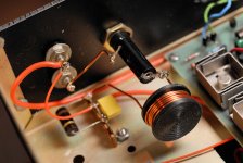
OK, here's my output inductor. I machined the bobbin out of Delrin. It has a 1" diameter by 0.375" wide winding window. I can't see exactly, but it looks like ten turns on the thing. The wire is AWG 16 solid magnet wire with single build insulation. You can't see it, but the other 10 ohm resistor is soldered directly across the back side of the inductor. For whatever reason I never had good luck with inductors wound on resistor bodies, regardless of resistor type. I think the form factor was just ineffective. This inductor measures 3.25 microhenries with a Q of 1.6 (@ 1kHz) and the DCR is about 13 milliohms, though I could be slightly off on that. (measured without the resistor on the back side) No doubt my construction is a bit wide open, but this amp was a "mule" that was taken apart and reassembled many times. I built it for development, not for compactness. Oddly, I built my first Tiger for compactness. It was impossible to service and had all sorts of oscillation problems. Had I known what I know now, I probably could have fixed it by changing the output inductor and a few other tweaks. That was many years ago and I ended up trashing the entire chassis and starting over. Too soon old, too late smart. Or at least not quite so dumb.
Attachments
Last edited:
Conrad,
Are you saying that moving the output inductor OFF the board causes the amp to become stable??
The improvement in the inductor itself noted, but is that a requirement for stability?
Is it one or both of the above - AND - if it is the second then what exactly is causing the problem using the stock inductor??
_-_-bear
Hi Bear,
The original Tiger inductor was never on the board, but was wired from some junction to the output connector or something- you'd have to look at the links way back at the beginning to see exactly. IMO, the improvement is the high-than-normal inductor value more than anything. I seem to remember that when Tigers have problems it occurs at something like 6 MHz. The inductor shown should maintain good behavior way beyond that. Also, FWIW, I did some very fussy amps some time back and the output inductor construction is more important than sometimes thought. Any core at all, even resistor wires, increases the THD over what you get with an air core inductor on an inert form. I don't know how important damping really is, considering wire resistance, but much amplifier damping is lost to resistance in the output wiring, including the inductor. The inductor shown gives good measurements at the amp terminals, if nowhere else!
The original Tiger inductor was never on the board, but was wired from some junction to the output connector or something- you'd have to look at the links way back at the beginning to see exactly. IMO, the improvement is the high-than-normal inductor value more than anything. I seem to remember that when Tigers have problems it occurs at something like 6 MHz. The inductor shown should maintain good behavior way beyond that. Also, FWIW, I did some very fussy amps some time back and the output inductor construction is more important than sometimes thought. Any core at all, even resistor wires, increases the THD over what you get with an air core inductor on an inert form. I don't know how important damping really is, considering wire resistance, but much amplifier damping is lost to resistance in the output wiring, including the inductor. The inductor shown gives good measurements at the amp terminals, if nowhere else!
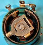
OK, I must eat my words on Tiger reliability! They do fail. The last couple times I powered the thing up, it was running hot. Measuring the bias on one channel showed several hundred mA, and the bias pot was only allowing it to be set high or near zero. After 31 years the Clarostat wire wound pot I had used for the bias adjustment failed. Actually the lubricant just hardened up and prevented contact. Photo of the guts below. I could have cleaned it, but decided to just replace the pair with new pots.
Now, you have to get up pretty early in the morning to blow up my stuff- I always install a safety resistor across my bias pots, so if they go open the amp won't be damaged by excess current. I had done so in this case and it paid off. Admittedly 31 years later, but it paid off.
BTW, I also looked at some notes from the last time I fooled with it, and I had reduced the feedback cap to 50 pF and increased the LF feedback cap to 1000 uF.
Attachments
New to this thread...
I know this is a rather old thread, but thought there was enough recent activity to warrant a post. Wondering if anyone has a working Tiger (of any variety) that they're not using anymore and it's been sitting in the basement or closet for years, if not decades, that they would be willing to sell (or donate,)?
In the mid-70's I attempted to build one of the first Tigers to appear in either Popular Electronics, or Radio-Electronics. Can't remember the exact model. I tried doing it from scratch, but using the SWTP design. However it died a quick death upon power up. I was a complete novice at the time (still am ) without the skill to troubleshoot and fix. Being a newly wed and in graduate school I was also on very limited funds.
Fast forward 35 yrs and I now have plenty of time to try and relive some of those early days of kit building that I simply could not afford at the time. Which brought me to.... 'I wondered whatever happened to SWTP' and their audio kit line. It's been refreshing to find the few threads here at DIYAudio, and some of you guys who have followed more closely the issues that plagued the early Tigers.
I don't really want to restore, or rebuild a non-functioning Tiger, but would like to find one to add to my ever growing vintage collection. If it happens to be in good shape and operational that would be a bonus.
If you have one you don't letting go of for cheap please leave me a PM.
Rick
I know this is a rather old thread, but thought there was enough recent activity to warrant a post. Wondering if anyone has a working Tiger (of any variety) that they're not using anymore and it's been sitting in the basement or closet for years, if not decades, that they would be willing to sell (or donate,
)?In the mid-70's I attempted to build one of the first Tigers to appear in either Popular Electronics, or Radio-Electronics. Can't remember the exact model. I tried doing it from scratch, but using the SWTP design. However it died a quick death upon power up. I was a complete novice at the time (still am
) without the skill to troubleshoot and fix. Being a newly wed and in graduate school I was also on very limited funds.Fast forward 35 yrs and I now have plenty of time to try and relive some of those early days of kit building that I simply could not afford at the time. Which brought me to.... 'I wondered whatever happened to SWTP' and their audio kit line. It's been refreshing to find the few threads here at DIYAudio, and some of you guys who have followed more closely the issues that plagued the early Tigers.
I don't really want to restore, or rebuild a non-functioning Tiger, but would like to find one to add to my ever growing vintage collection. If it happens to be in good shape and operational that would be a bonus.
If you have one you don't letting go of for cheap please leave me a PM.
Rick
Hey bear - If you change your mind drop me a PM. I'd gladly pay shipping. In the mean time I'll keep looking, and hopefully with a few that read this thread something may shake loose.I'd gladly give you mine for the cost of shipping BUT I have the overwhelming need to find the time to repair one and put a baker clamp in to see if that prevents it from self immolation or not!
_-_-bear
PS. it's on my bucket list...
I've noticed there's - what appears to be a very clean looking - set of Tiger .01 on ebay, but for a price. Almost brand new looking! I don't want one that bad yet.
Rick
SWTP Universal MKII Selling. . . . maybe
Hello, I registered and made a post or two awhile ago and happened upon this thread. I was an avid SWTP fan back in the early 70s when I was in an Air Force tech school in Texas in 1970 and built everything from a function/signal generator (still have it and use it!), some other audio kits like a couple of the "color organ" light boxes that flashed lights in tempo and frequency to music, and in 1972, two Universal Tiger MKII amps. I still have most, if not all, of the original documentation, a couple of the little mailing catalogs that they sent to me almost every month, and the UT MKII's along with some original spare parts.
I have been an electronics tech since then and worked in several field service and in house repair jobs over the years. I last fired up the UT MKIIs a few years ago and they worked and measured fine. They have been in storage mostly since 1975 when I got my Phase Linear equipment, but I used them for several years even then in another room occasionally. I'm sure they could use some check up and such to verify filter caps are ok, crossover pots set right, etc. I no longer have a working scope and can't easily check or adjust crossover on it and have so much other audio equipment I am thinking of selling them on Ebay or if someone may want them here.
They are installed in a custom made solid walnut cabinet with plenty of venting and even an additional "muffin" fan that I really never needed to use. The cabinet is complete with an aluminum face plate and two large illuminated VU meters I purchased from Lafayette Electronics back in the day. I used to drive the UT MKII pair with a Dynaco PAT-4 and FM-5 Tuner which I also still have in matching solid walnut custom cabinets that looked great with the UT MKII. When I get a chance between projects I will post some pictures after I locate all the documentation I have in one of several file cabinets that are stuffed with years of electronics owners manuals.
I'm just writing this to to give a heads up to anyone who might be interested in a purchase down the road. The units were never abused and I even have a pair of test chart results from when McIntosh Clinics were held in various HiFi shops around the country. As I remember, the UT MKIIs held there own and surprised the Mac technicians! If I sell these units I expect I would get a good price for them since I also have one or two sets of MJ output transistors and other drive components I bought as "spares". . . . I was always a bit OCD about having spares!
I'll WILL post pictures when I have a bit of time to dig things out of storage and if I get any interest.
- Home
- Amplifiers
- Solid State
- Universal Tiger