Re: Re: FET vs. BJT
Hi Jan,
I don't think so. Both circuits have very low noise and the surface noise of the LP is way larger than that of the circuit. It is not the noise I hear but the timbre of the tone, especially on voices or the clavichord.
My idea is that the further you go back to the source the more important it is. Hence a preamp influences the sound more than a poweramp grossly speaking. Seems logical to me as the chain further amplifies any distortion in the source component.
But again why all this theoretical hand waving? In real world you have to use a FET, a BJT or a tube. Pick your choice! Go building!

janneman said:
Elso,
With Andy's post in mind, could it be that your preference is influenced by differences in noise factors? You seem to imply that the lower the signal (prepre) the larger your preference for fets. If it was the linearity it would be the opposite, as smaller signals diminish the advantage of the fet.
Jan Didden
Hi Jan,
I don't think so. Both circuits have very low noise and the surface noise of the LP is way larger than that of the circuit. It is not the noise I hear but the timbre of the tone, especially on voices or the clavichord.
My idea is that the further you go back to the source the more important it is. Hence a preamp influences the sound more than a poweramp grossly speaking. Seems logical to me as the chain further amplifies any distortion in the source component.
But again why all this theoretical hand waving? In real world you have to use a FET, a BJT or a tube. Pick your choice! Go building!
Re: Re: Re: FET vs. BJT
Hi Elso,
Yeah, building. I've had those years churning out a new power amp, preamp, dig controlled attenuator and what have you at the rate of one per month or so. These days, with all the demands on my time, I can't seem to go forward. I have a few things in the works, but progress is slow.
Anyway, no need for this dicussion for me to duplicate your work, I think. I'm not challenging in any way your findings. It's just that I am so curious: a cause is proposed for a certain effect, then we take that cause apart and find that it is unlikely to cause the effect, but the effect remains! Aren't you also curious what the REAL cause is? Like peeling an onion layer by layer, everytime you think you got is, it's just another layer to peel back.
Listening tells you there is an effect; it doesn't tell you why. For that you need to think, reason, be vrey critical, measure.
Like this discussion: I think the power amp influences the sound more then the preamp, because generally is has more distortion. Although the power amp amplifies the small preamp and source distortions, that doesn't increase the distortion %! In other words, multiplying a preamp distorted signal by say 26 doesn't increase the % THD!
But the power amp does ADD its own distortions, which are generally larger then those of the preamp. So you see Elso, you can learn a lot just by reasoning, which after all is the title of this thread.
Like the discussion I had with Pavel on the reason why he feels buffered preamp drivers are always sounding better. (And I take the blame for letting that discussion derail). The proposed cause, namely less opamp thermal and cap current stress turned out to be unlikely because in typical cases the output current asked from the opamp is quite low. That fascinates me, and I start searching for another possible cause.
BTW We missed you last weekend in Veldhoven. Aalt-Jouk was stalking the corridors as usual, and I attended a nice half hour presentation by Ken Ishawatha, Marantz's lead designer on a historic tour of hi-fi (actually Maranz). He started by playing a mono record from 1948 or something, which sounded surprisingly good. I though it sounded better than some of the later SACD disks played, in the sense of more enjoyable, although of course the SACD was more 'perfect' in an absolute sense, no doubt about that.
Oh well, let me see if I can make some progress this weekend on my rebuilding of a pair of Jean Hiraga's one-mosfet power amps. And then there are the proto boards for the Hawksford-corrected output stage to try out....
Have fun.
Jan Didden
Elso Kwak said:Hi Jan,
[snip]My idea is that the further you go back to the source the more important it is. Hence a preamp influences the sound more than a poweramp grossly speaking. Seems logical to me as the chain further amplifies any distortion in the source component.
But again why all this theoretical hand waving? In real world you have to use a FET, a BJT or a tube. Pick your choice! Go building!

Hi Elso,
Yeah, building. I've had those years churning out a new power amp, preamp, dig controlled attenuator and what have you at the rate of one per month or so. These days, with all the demands on my time, I can't seem to go forward. I have a few things in the works, but progress is slow.
Anyway, no need for this dicussion for me to duplicate your work, I think. I'm not challenging in any way your findings. It's just that I am so curious: a cause is proposed for a certain effect, then we take that cause apart and find that it is unlikely to cause the effect, but the effect remains! Aren't you also curious what the REAL cause is? Like peeling an onion layer by layer, everytime you think you got is, it's just another layer to peel back.
Listening tells you there is an effect; it doesn't tell you why. For that you need to think, reason, be vrey critical, measure.
Like this discussion: I think the power amp influences the sound more then the preamp, because generally is has more distortion. Although the power amp amplifies the small preamp and source distortions, that doesn't increase the distortion %! In other words, multiplying a preamp distorted signal by say 26 doesn't increase the % THD!
But the power amp does ADD its own distortions, which are generally larger then those of the preamp. So you see Elso, you can learn a lot just by reasoning, which after all is the title of this thread.
Like the discussion I had with Pavel on the reason why he feels buffered preamp drivers are always sounding better. (And I take the blame for letting that discussion derail). The proposed cause, namely less opamp thermal and cap current stress turned out to be unlikely because in typical cases the output current asked from the opamp is quite low. That fascinates me, and I start searching for another possible cause.
BTW We missed you last weekend in Veldhoven. Aalt-Jouk was stalking the corridors as usual, and I attended a nice half hour presentation by Ken Ishawatha, Marantz's lead designer on a historic tour of hi-fi (actually Maranz). He started by playing a mono record from 1948 or something, which sounded surprisingly good. I though it sounded better than some of the later SACD disks played, in the sense of more enjoyable, although of course the SACD was more 'perfect' in an absolute sense, no doubt about that.
Oh well, let me see if I can make some progress this weekend on my rebuilding of a pair of Jean Hiraga's one-mosfet power amps. And then there are the proto boards for the Hawksford-corrected output stage to try out....
Have fun.
Jan Didden
Jan,
my proposed reason is HF interference, even from the sound source or induced (and its isolation from the opamp). This has always been written on my web pages. Even though I do not understand the dramatic improvement when using very small series resistor (like 5 Ohm) at the buffered preamp output and/or cable termination. I was also thinking about non-linear cable dielectric behavior.
All the best,
Pavel
I was also measuring the spectral content at the output of CD players above 22.05 kHz. I will prepare the english version of the page.
exponential has both even & odd harmonics
No, if we remember the Taylor series for e^x, it is:
e^x = 1 + x + (x^2)/2! + (x^3)/3! + ...,
or the summation of (x^n)/n!, n = 0 to infinity. Both even and odd terms are present.
Any reference text on mathematics will confirm this. Best regards.
originally posted by Swedish Chef
Elso, not at the core of this discussion but anyway here is a short answer. If you do a Taylor series expansion of the exponential function you end up with a polynomial with all odd exponents. In the frequency domain that translates to odd (3rd, 5th, 7th etc) harmonics for a BJT.
No, if we remember the Taylor series for e^x, it is:
e^x = 1 + x + (x^2)/2! + (x^3)/3! + ...,
or the summation of (x^n)/n!, n = 0 to infinity. Both even and odd terms are present.
Any reference text on mathematics will confirm this. Best regards.
PMA said:Jan,
my proposed reason is HF interference, even from the sound source or induced (and its isolation from the opamp). This has always been written on my web pages. Even though I do not understand the dramatic improvement when using very small series resistor (like 5 Ohm) at the buffered preamp output and/or cable termination. I was also thinking about non-linear cable dielectric behavior.
All the best,
Pavel
[snip]
Pavel, thanks for your reaction.
Hmm yes. Without the series resistor the buffer output will be hit by the full interference signal, if that is the cause, which may be a bit too much. With a little series resistor, the output impedance may still be low enough to damp the interference but at the same time give enough attenuation w.r.t. the buffer output impedance to help the buffer to cope with it. A bit speculative maybe, but there is some logic to it. Now how to test that hypothesis...
Jan Didden
Jan,
just to clarify, I have been testing various resistors at the buffer output, from 1k down over 100 Ohm, 50 Ohm to 5 Ohm. I have not tried direct output (Rs=0) yet. The reason was the scope wideband measurement. Yes, with 5 Ohm it was better than with 0 Ohm. The buffer is unconditionally stable with capacitive load up to order of uF, even for Rs=0.
just to clarify, I have been testing various resistors at the buffer output, from 1k down over 100 Ohm, 50 Ohm to 5 Ohm. I have not tried direct output (Rs=0) yet. The reason was the scope wideband measurement. Yes, with 5 Ohm it was better than with 0 Ohm. The buffer is unconditionally stable with capacitive load up to order of uF, even for Rs=0.
lumanauw said:But NE5532 have an interesting property. Once I series 8 of these opamps in buffer mode. The final result, the array of these 8 buffers with NE5532 gives no (little) difference with the real input sound. With other opamps, the difference is bigger, so other opamps are"making" their own sound, instead of reproducing what is fed to them.
Hi Lumanauw
You nail it...output equal to the input...this is the essence of the null test.
Try to do a null test between a NE 5532 and the OPA 2604...you will be surprised.
The sound of a series of amps ,tell us much about the linearity of each one .As the no linearity adds and become much more audible.
After all , because of the problem of the added distortion in a series of amps ,that was a problem in the repeaters amps in the telephone lines, that Harold S. Black bring us the Negative Feedback.
Great minds think alike!!...
More about op amps here:
http://fnt-www.ss.titech.ac.jp/~hajime/uec/distortion/opa.html
Cheers
are we losing track of our reasoning?
returning to input diff pair distortions (really, really consider starting new threads, this thread is way unwieldy with just input stage distortion discussion going on)
To illustrate the some points about the relative gain/distortion tradeoffs of bjt vs fet diff pair inputs I’ve simulated a perfectly linear model amp with a un/degenerated bjt diff pair vs a fet diff pair input
In this sim I am trying to eliminate everything except diff pair input stage gm nonlinearity, the current mirror (V2, F1) nearly eliminates 2nd order nonlinearity, to exclude dynamic nonlinearity from bjt/fet nonlinear junction C I scaled frequency down, feedback impedance is low to eliminate base current effects
With the current mirror the gain intercept for this sim is 436 Hz for the bjt diff pair (closed loop gain = +14, GBW = 14 * 432 Hz = 6.1 KHz, just scale up frequencies by ~1-2K and C1 down by the same ratio to get back to typical audio amp numbers)
The test signal is a 10 Hz sine, amplitude modulated with a 1 Hz sine (“unbalanced” to preserve the carrier this time ‘round) – BTW, I believe this would be a good sim approach to Gilbert’s analysis, similar GBW ratio, slightly more gain and the amplitude of the test signal is “automatically” swept by the AM modulation – no need for andy_c’s math sw skills, anyone competent to seriously modify or design their own audio amps should be able to use spice at this level, feel free to modify and examine whatever phase/IMD ratio you want in (free) Lt Spice
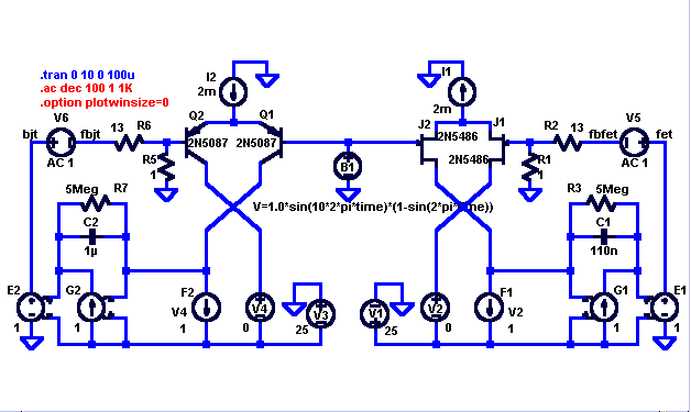
The first fft is an “unfair” comparison, just dropping in fets in place of the bjts isn’t a clear distortion win (the unfairness comes from the loop gain reduction with lower fet gm)
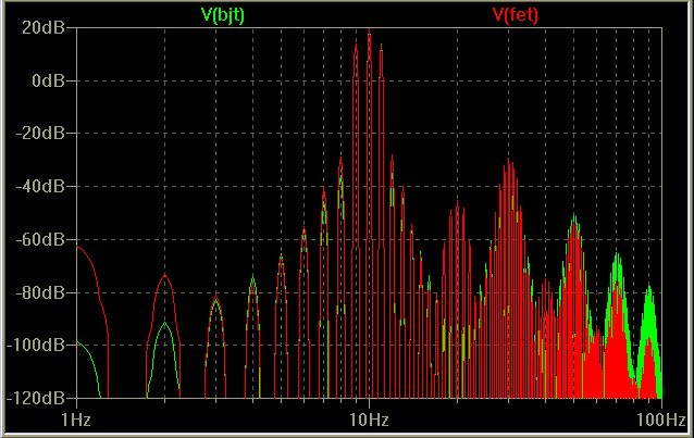
The second fft evens up the loop gain/GBW by decreasing C1 for the fet input circuit, now the fet looks pretty good – but I maintain this is still an unfair comparison, we just added nearly 20 dB loop gain to make up for the fet’s low gm
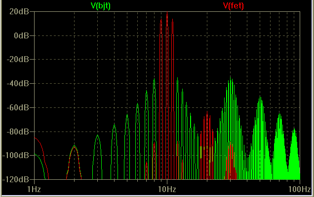
A final, more even-handed comparison adds 210 Ohm degeneration Rs to the bjt emitters which lowers the diff pair stage gm to the same level as the fet input while providing local linearizing feedback, and adds the same loop gain to both by setting C1=C2= 110n
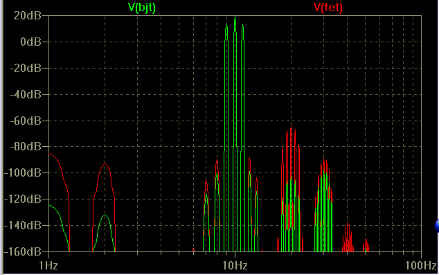
Note that to even see any higher order distortion in the degenerated bjt stage I’ve extended the dB scale down to -160 dB (a tiny spot of green shows @ -160 dB, 50Hz - the fifth harmonic)
I think this shows you need to consider device gain, local and global feedback together to evaluate the roles of nonlinearity vs gain, bjts have more gain (when gm is the important parameter) than fets, enough more gain that local feedback linearization can give better distortion results with the bjt devices at equivalent gm
returning to input diff pair distortions (really, really consider starting new threads, this thread is way unwieldy with just input stage distortion discussion going on)
To illustrate the some points about the relative gain/distortion tradeoffs of bjt vs fet diff pair inputs I’ve simulated a perfectly linear model amp with a un/degenerated bjt diff pair vs a fet diff pair input
In this sim I am trying to eliminate everything except diff pair input stage gm nonlinearity, the current mirror (V2, F1) nearly eliminates 2nd order nonlinearity, to exclude dynamic nonlinearity from bjt/fet nonlinear junction C I scaled frequency down, feedback impedance is low to eliminate base current effects
With the current mirror the gain intercept for this sim is 436 Hz for the bjt diff pair (closed loop gain = +14, GBW = 14 * 432 Hz = 6.1 KHz, just scale up frequencies by ~1-2K and C1 down by the same ratio to get back to typical audio amp numbers)
The test signal is a 10 Hz sine, amplitude modulated with a 1 Hz sine (“unbalanced” to preserve the carrier this time ‘round) – BTW, I believe this would be a good sim approach to Gilbert’s analysis, similar GBW ratio, slightly more gain and the amplitude of the test signal is “automatically” swept by the AM modulation – no need for andy_c’s math sw skills, anyone competent to seriously modify or design their own audio amps should be able to use spice at this level, feel free to modify and examine whatever phase/IMD ratio you want in (free) Lt Spice

The first fft is an “unfair” comparison, just dropping in fets in place of the bjts isn’t a clear distortion win (the unfairness comes from the loop gain reduction with lower fet gm)

The second fft evens up the loop gain/GBW by decreasing C1 for the fet input circuit, now the fet looks pretty good – but I maintain this is still an unfair comparison, we just added nearly 20 dB loop gain to make up for the fet’s low gm

A final, more even-handed comparison adds 210 Ohm degeneration Rs to the bjt emitters which lowers the diff pair stage gm to the same level as the fet input while providing local linearizing feedback, and adds the same loop gain to both by setting C1=C2= 110n

Note that to even see any higher order distortion in the degenerated bjt stage I’ve extended the dB scale down to -160 dB (a tiny spot of green shows @ -160 dB, 50Hz - the fifth harmonic)
I think this shows you need to consider device gain, local and global feedback together to evaluate the roles of nonlinearity vs gain, bjts have more gain (when gm is the important parameter) than fets, enough more gain that local feedback linearization can give better distortion results with the bjt devices at equivalent gm
Attachments
Hi jcx !
Nice demonstration, but maybe you should have picked a more
representive jfet. Why did you use p-channel-jfets ?
I suggest you turn the circuit upside-down, and use a nchanneljfet
like the sk170. It still has lower gm than most bjts, but only most.
(And of course use the complementary of the 2n5087.)
If i remember correct, you need RE's < 10ohm for bjts to get same
gm. Now you could say, ok let's use one of best bjts for this test,
for example the mpsa18. Hmpf... would be interesting, sk170 against mpsa18 ?
I'm at work now and can't simulate.
Mike
MikeB said:Why did you use p-channel-jfets ?
MikeB, it's N-channel. You just need to turn your head upside down

jcx said:The second fft evens up the loop gain/GBW by decreasing C1 for the fet input circuit, now the fet looks pretty good – but I maintain this is still an unfair comparison, we just added nearly 20 dB loop gain to make up for the fet’s low gm
That was the case I was thinking of in my earlier conversation with Jan. Lowest noise case, equal gain-bandwidth product. Seems fair to me. Sounds like the usual "reduce gm and reduce Ccomp for the same gain-bandwidth product" trick. Although I guess if the compensation cap is very small to begin with, this isn't possible.
As usual, another interesting and informative post from jcx.
Re: are we losing track of our reasoning?
Excellent job jcx, now:
Though this is true from a systems viewpoint, please let me suggest this test does not compare bjt vs. fet gm. We might say - borrowing from tube nomenclature - you are comparing mu (voltage gain) for you are loading collector / drain with high impedance.
A true gm test should load collector / drain with short circuits and should measure current (i.e. input voltage vs. output current). Probably a more accurate - and realistic considering popular circuit topologies - could be a cascode configuration where the low impedance loading approaches the short circuit condition.
Rodolfo
Excellent job jcx, now:
jcx said:I think this shows you need to consider device gain, local and global feedback together to evaluate the roles of nonlinearity vs gain, bjts have more gain (when gm is the important parameter) than fets, enough more gain that local feedback linearization can give better distortion results with the bjt devices at equivalent gm
Though this is true from a systems viewpoint, please let me suggest this test does not compare bjt vs. fet gm. We might say - borrowing from tube nomenclature - you are comparing mu (voltage gain) for you are loading collector / drain with high impedance.
A true gm test should load collector / drain with short circuits and should measure current (i.e. input voltage vs. output current). Probably a more accurate - and realistic considering popular circuit topologies - could be a cascode configuration where the low impedance loading approaches the short circuit condition.
Rodolfo
Re: are we losing track of our reasoning?
JCX,
This is a very revealing post! Great job, wish I could have done it...
Anyway, it does show that naked device properties are interesting, but the real issue is how they behave in the context of the circuit topology.
Jan Didden
jcx said:[snip]To illustrate the some points about the relative gain/distortion tradeoffs of bjt vs fet diff pair inputs I’ve simulated a perfectly linear model amp with a un/degenerated bjt diff pair vs a fet diff pair input[snip]
JCX,
This is a very revealing post! Great job, wish I could have done it...
Anyway, it does show that naked device properties are interesting, but the real issue is how they behave in the context of the circuit topology.
Jan Didden
No, if we remember the Taylor series for e^x, it is:
e^x = 1 + x + (x^2)/2! + (x^3)/3! + ...,
or the summation of (x^n)/n!, n = 0 to infinity. Both even and odd terms are present.
Oops!
 You are absolutely right, I was totally wrong. Mixed it all up with the Taylor series for arctan.
 Nevertheless, the BJT produces "nastier" distortion components than the FET from an human hearing point of view. Unless minimized by feedback...
/M
- Status
- This old topic is closed. If you want to reopen this topic, contact a moderator using the "Report Post" button.
- Home
- Amplifiers
- Solid State
- "What's your reasoning?" and not "What's your belief?".
