You mean miller cap in ordinary VAS?...or you simply swamp Ccb with a large, external capacitor.Capacitors are nice and linear compared with introducing another distorting device in the signal path.
MikeB said:
A classical 2nd harmonic, this time 180°...
Mike
Ooops, 90° of course...
Hello to all. I thought it might be helpful to add to John Curl's comments on resurrecting the Barrie Gilbert articles. I requested permission to post them over the weekend, and am awaiting a response. When that is received they will be posted on my web site. Despite all of the fuss, this material is worthy of study!
Also, some further comments on the mechanism of PIM occur to me. As outlined in my ED article (see http://home.comcast.net/~walt-jung/wsb/PDFs/WTnT_Op_Amp_Audio_3.pdf ), one can combat this in a few ways. One is simply to load the integrator with a resistor. This caps the open loop (OL) gain, and moves out the OL corner frequency. An example cited was the AD829, which has the high-Z node available to do this. Coincidentally, I just had an email from a fellow who was in the process of doing this exact thing with an AD829. Of course, it isn't limited to just the 829, the AD844 will also work like this. Add the resistor from pin 5 to GND. Then you don't need to argue about whether the old or the new AD844 DS is correct... just make the OL BW what you want! Note that this approach to reducing PIM does not actually reduce the gm nonlinearity. Instead, it removes the phase changes within the audio range, which in turn makes any instantaneous changes in gm relatively innocuous.
The cited article above goes into comparisons between bipolar and FET input stages in op amps, and their relative linearities. It is readily apparent that the bipolar type is much more nonlinear than a comparable one using FETs, if this wasn't already obvious from the math of Barrie Gilbert.
Walt Jung
Walt,
Welcome back, and thanks for all your efforts with the Gilbert article.
When I get the time, I'd like to extend the math of that article in the following two ways:
1) Assume a finite DC open-loop gain in the amplifier (Gilbert assumes an infinite DC open-loop gain [integrator]).
2) Allow for the substitution of arbitrary Taylor series expansion coefficients for the input stage characteristic (Gilbert assumes the classic tanh() characteristic, which only applies to the case of an un-degenerated bipolar input stage).
Hopefully this will stimulate further constructive discussion.
And I thank you for the comments on my efforts, along with John's. It forced me to get a good HTML editor, so if all else is lost, I'm still ahead.
On your point two, see:
IEEE JOURNAL OF SOLID-STATE CIRCUITS, VOL. 33, NO. 1, JANUARY 1998
The Multi-tanh Principle: A Tutorial Overview
Barrie Gilbert, Fellow, IEEE
This goes into great detail on extension of this bipolar input stage for greater linearity.
Walt Jung
PS: I hope you can forgive my ignorance here, but what is the "c" in andy_c?
Of course, it isn't limited to just the 829, the AD844 will also work like this. Add the resistor from pin 5 to GND. Then you don't need to argue about whether the old or the new AD844 DS is correct... just make the OL BW what you want! Note that this approach to reducing PIM does not actually reduce the gm nonlinearity. Instead, it removes the phase changes within the audio range, which in turn makes any instantaneous changes in gm relatively innocuous.
Walt Jung [/B]
Walt,
thank you very much for your input.
Your articles in Electronic Design were the key for me to understand opamp related restrictions.
Best regards,
Pavel
Walt,
thank you very much for your input.
Your articles in Electronic Design were the key for me to understand opamp related restrictions.
Best regards,
Pavel
Thank you, Pavel, for stating that.
Gee, I even wish that I was doing those columns again, as they were fun! But with all of the shrinkage going on in the printed press, it'll likely not happen.
Walt Jung
WaltJ said:[snip] One is simply to load the integrator with a resistor. This caps the open loop (OL) gain, and moves out the OL corner frequency. An example cited was the AD829, which has the high-Z node available to do this. Coincidentally, I just had an email from a fellow who was in the process of doing this exact thing with an AD829. Of course, it isn't limited to just the 829, the AD844 will also work like this. Add the resistor from pin 5 to GND. Then you don't need to argue about whether the old or the new AD844 DS is correct... just make the OL BW what you want! Note that this approach to reducing PIM does not actually reduce the gm nonlinearity. Instead, it removes the phase changes within the audio range, which in turn makes any instantaneous changes in gm relatively innocuous.[snip]Walt Jung
Hi Walt,
Welcome back! Good to see you're still alive and kicking.
I THINK I understand your above post, but please bear with me. This method limits the gain below the OL bandwidth, like slicing off the part between DC and Fc to make it level until Fc, correct? So, as you say, it doesn't change the basic Gm non-linearity, which is located in the diff input pair.
And since the phase changes are related to whatever impedance drives the Vas stage into Cc, by parallelling the Vas Zout with a resistor we lower the RC time constant thus lowering phase shift, right?
Does this not actually extend the apparent Fc, as the turnover freq is now determined by a lower RC constant?
Jan Didden
PS Must check into the AD829...
Yes, I agree with youir paragraph 1.
Well, not quite I think, for para 2. You introduce the VAS terminology, which doesn't relate to the AD844, a current feedback type. The internal Z is referenced to GND (or the supplies), and is high. Part of it is the high Z of the current sources feeding it, part of it the Cc in parallel. The external R shunts this Z, which effectively lowers the dynamic Z (assuming Cc is constant). The total OL gain is lowered, and the OL break frequency is pushed up. Gain has been traded for BW. The phase now is relatively constant with freq., since the OL gain is flat in the audio band.
As for your para 3, I don't think I quite understand it. Remember that you can't change the Gain*BW with this trick, so if you lower Gain (by the shunt R), the OL BW must go up, to maintain the same G*BW.
Walt Jung
more high gain reasoning
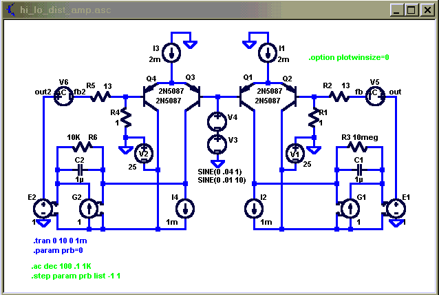
Simple Miller Compensated Voltage Amp test circuit,
Right circuit high loop gain, left low gain – 10 KOhm R6 resistive local VAS feedback lowering open loop gain to ~20 dB, same GBW as high gain

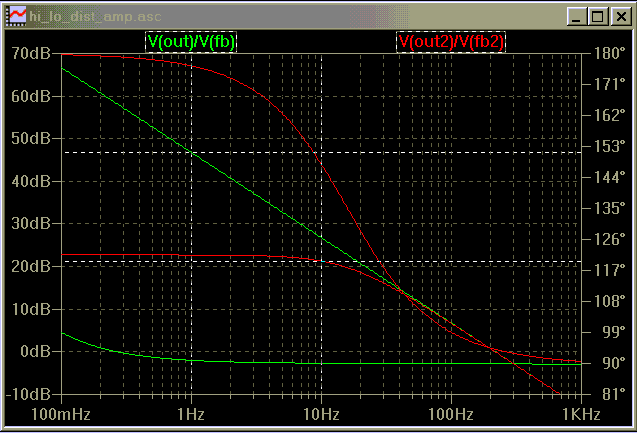
loop gain plots green high gain, red low gain ( V5,6 are 1 V AC sources for the loop gain plot )

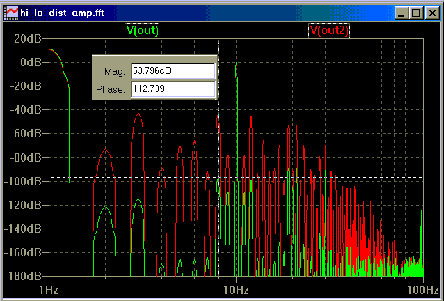
2 tone 4:1 1,10 Hz distortion spectrum, 0.5 V peak input signal amplitude; green high gain, red low
(4:1 amplitude ratio for lo:hi frequency components is commonly used since it is assumed that low frequencies will typically be larger in amplitude; music is commonly asserted to have ~ 3KHz power bandwidth)

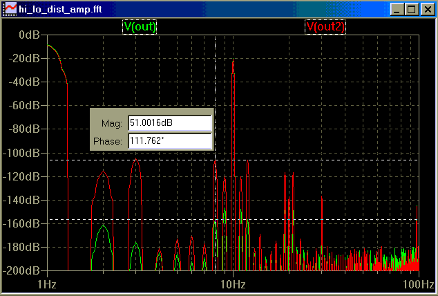
same with only 0.05 V peak input signal amplitude; green high gain, red low - shows scaling of distortion products follows theory, 20 dB less signal amplitude, 60 dB less distortion product ( but dist/signal ratio improves 40 dB as previously discussed)

the major distortion source is the tanh nonlinearity of the diff input transistors, to focus on this effect consider the 8 Hz IM product from the dominant 3rd order nonlinearity (10 Hz - 2* 1 Hz )
in the distortion spectrum plots we see >50 dB more of this IM distortion product with the low gain amp (red) than in the high loop gain amp, looking at the phase diff from the cursor diff inset we also see that the green and red 8 Hz IM products differ in phase by 112 dgrees ~= the 90 degree phase diff characteristic of FM vs AM modulation products I showed in post # 80 – presumably the green is nearly pure “FM” modulation type distortion
this sim illustrates why some of us have a hard time accepting the low gain/high bandwidth approach – the high gain approach will always have less differential input signal amplitude at low frequencies which hugely reduces the distortion amplitude in the bjt diff pair – FM/PIM distortion would have to be shown to be orders of magnitude more objectionable than AM IM products for an engineer to choose to lower open loop gain at low frequencies to change the phase relations of the IM distortion products from that characterized as “FM” modulation distortion to the supposedly less objectionable “AM” IM distortion product phase relationship
Simple Miller Compensated Voltage Amp test circuit,
Right circuit high loop gain, left low gain – 10 KOhm R6 resistive local VAS feedback lowering open loop gain to ~20 dB, same GBW as high gain

loop gain plots green high gain, red low gain ( V5,6 are 1 V AC sources for the loop gain plot )

2 tone 4:1 1,10 Hz distortion spectrum, 0.5 V peak input signal amplitude; green high gain, red low
(4:1 amplitude ratio for lo:hi frequency components is commonly used since it is assumed that low frequencies will typically be larger in amplitude; music is commonly asserted to have ~ 3KHz power bandwidth)

same with only 0.05 V peak input signal amplitude; green high gain, red low - shows scaling of distortion products follows theory, 20 dB less signal amplitude, 60 dB less distortion product ( but dist/signal ratio improves 40 dB as previously discussed)

the major distortion source is the tanh nonlinearity of the diff input transistors, to focus on this effect consider the 8 Hz IM product from the dominant 3rd order nonlinearity (10 Hz - 2* 1 Hz )
in the distortion spectrum plots we see >50 dB more of this IM distortion product with the low gain amp (red) than in the high loop gain amp, looking at the phase diff from the cursor diff inset we also see that the green and red 8 Hz IM products differ in phase by 112 dgrees ~= the 90 degree phase diff characteristic of FM vs AM modulation products I showed in post # 80 – presumably the green is nearly pure “FM” modulation type distortion
this sim illustrates why some of us have a hard time accepting the low gain/high bandwidth approach – the high gain approach will always have less differential input signal amplitude at low frequencies which hugely reduces the distortion amplitude in the bjt diff pair – FM/PIM distortion would have to be shown to be orders of magnitude more objectionable than AM IM products for an engineer to choose to lower open loop gain at low frequencies to change the phase relations of the IM distortion products from that characterized as “FM” modulation distortion to the supposedly less objectionable “AM” IM distortion product phase relationship
Attachments
WaltJ said:I hope you can forgive my ignorance here, but what is the "c" in andy_c?
Well, that would be the first letter of my last name
BTW, I just finished up going through Gilbert's analysis, duplicating his math. The typesetting of the original EDN article is hard to read. I finally realized what John had been saying about PIM and open-loop bandwidth, and it hit me what the real, root cause of the AM to PM conversion was.
I realized that the concept of modulating the instantaneous gain-bandwidth product was not the way to look at the problem. The phase modulation comes about from a gain compression in the path from the differential input to the output. But because the differential input voltage is in quadrature phase with the output, this level-dependent gain compression becomes a level-dependent phase shift when referenced back to the op-amp input proper. If the differential input were in phase with the output at all frequencies, then the AM to PM conversion could never occur.
But if you want essentially zero AM to PM conversion, you pay big time in terms of overall linearity. To completely eliminate AM to PM conversion over the audio band, you'd need an open-loop bandwidth of 10x the audio band (to get essentially zero phase shift of the open-loop gain). Also, the gain compression term that causes the level-dependent phase is proportional to the differential input voltage amplitude squared. I could envision a situation where the phase shift would be reduced by increasing the open-loop bandwidth, but this ends up reducing the open-loop gain as well. If this were done by, say 10x or 20 dB, the phase shift of the open-loop gain would be closer to zero than before, but the amplitude portion of the error term would blow up by 100x. So for some cases where the open-loop phase shift is not identically zero, I could see the possibility of doing more harm than good for just PIM by increasing open-loop bandwidth. It's hard to say. I'll have to try extending the analysis to finite DC open-loop gain as I mentioned before, and also arbitrary cubed term in the Taylor series expansion of first stage current vs differential input voltage.
I could envision doing some 3d graphs. On the x axis would be input (or output) level. On the y axis would be the difference between the actual phase and the ideal phase (ideal = linear system). Coming out of the page on the z axis would be frequency.
All sorts of combinations could be tried. Another thing I was thinking of was evaluating linearized input stages like the compound pair I posted earlier. It should be possible to determine using SPICE and some external data analysis the cubed term in the Taylor series expansion of Iout vs Vin by numerical differentiation of those curves. The mind boggles...
What really bugs me about all this is that a decision to completely wipe out the PIM by increasing open-loop bandwidth is almost like saying that all other forms of nonlinearity are completely irrelevant. That approach hurts TIM as well as other nonlinearities that are simpler AM to AM conversion.
Ah well. Enough babbling...
Re: more high gain reasoning
That's my concern as well. Nice plots and summary there. They provide a dramatic illustration of the issue. I was wondering how you did IM using the FFT in one of your previous posts, but then I realized all your sidebands have this nice integer relationship. Very cool
jcx said:FM/PIM distortion would have to be shown to be orders of magnitude more objectionable than AM IM products for an engineer to choose to lower open loop gain at low frequencies to change the phase relations of the IM distortion products from that characterized as “FM” modulation distortion to the supposedly less objectionable “AM” IM distortion product phase relationship
That's my concern as well. Nice plots and summary there. They provide a dramatic illustration of the issue. I was wondering how you did IM using the FFT in one of your previous posts, but then I realized all your sidebands have this nice integer relationship. Very cool
Hi jcx,
forgive me, but where is the point by using an AC-sweep up to 1khz ?
Wasn't it obvious that for low freqs high olgain/feedback is better ?
I thought the concern was dynamic phaseshifting when ol-bandwidth
reaches it's cornerfreq ?
Or did i understand everything wrong ?
I understood that high olgain is not the problem, it's the resulting
low ol-bandwidth, giving frequencydependent delay from input to output.
Mike
You can think of the frequency in his display as normalized frequency. To scale the frequency by x, just divide the compensation cap by x (note that it has a large value also). For the FFT to work correctly without DFT leakage, all the intermod products have to be an integer multiple of a common frequency. My guess is that jcx just picked a low, normalized frequency to make the frequency computations simple.
Also, the issue with PIM is a level-dependent phase shift from input to output, not a frequency-dependent one. The Gilbert article gives an excellent analysis of this, but you have to slog through all the math. PIM can't occur if the differential input voltage is in phase with the output. But to get this, you end up being wiped out by normal, AM-to-AM intermods. His post, I think, was meant to illustrate to what extent that wipeout will occur.
Also, the issue with PIM is a level-dependent phase shift from input to output, not a frequency-dependent one. The Gilbert article gives an excellent analysis of this, but you have to slog through all the math. PIM can't occur if the differential input voltage is in phase with the output. But to get this, you end up being wiped out by normal, AM-to-AM intermods. His post, I think, was meant to illustrate to what extent that wipeout will occur.
Well, that would be the first letter of my last name . It's a crazy world though. I'd hate for my employer to do a search on my name and find that I posted something here while I was waiting for my project to compile at work. It's paranoid I know, but I work in a dog-eat-dog environment. Better safe than sorry.
Sorry that you wouldn't take the suggestion to allow folks to address you properly. It appears that you have had a lot to say worthy of reading. My point was (however subtle) that it behooves people to stand up and be known. They will gain greater respect for it.
Walt Jung
WaltJ said:
Sorry that you wouldn't take the suggestion to allow folks to address you properly. It appears that you have had a lot to say worthy of reading. My point was (however subtle) that it behooves people to stand up and be known. They will gain greater respect for it.
Walt Jung
Hi Walt,
Well, all my friends have called me Andy since kindergarten, so I consider that being addressed properly
"PIM is a level-dependent phase shift from input to output, not a frequency-dependent one."
Okay, in this case it's something completely different ! Sorry...
But now another thing ! As i stated in a previous post, PM seems
to behave like even harmonics, means it should go with a fully
complementary design ?
I observed this PM only in asymetrical circuits, i called it "asymetrical
slewrate". (the sin(F1+sin(F1)*0.4) thing)
Or again wrong ?
Mike
- Status
- This old topic is closed. If you want to reopen this topic, contact a moderator using the "Report Post" button.
- Home
- Amplifiers
- Solid State
- "What's your reasoning?" and not "What's your belief?".