jcarr said:Bricolo, does this help?
http://www.diyaudio.com/forums/showthread.php?postid=119592#post119592
I prefer to use active current sources rather than collector resistors.
regards, jonathan carr
Yes, it helped explaining the mechanism.
Now I have to learn how to bias it properly.
Which component (or component ratio) sets the gain in a folded cascode?
Current from the CE transistor is reflected down into the CB transistor with a gain of 1. The CB transistor itself has a current gain of 1, so the output is exactly the same as the current from the CE stage. Thus the gain depends on the gm of the CE transistor. Gain can be varied by altering the tail current of the differential (note that the current supplied by the two top current sources must be at least equal to the current from the tail current source so that there is some spare to bias the cascode).
Don't know how clear that is. I know of no sources on the internet dealing with things like this, but if you can find a good book on op-amp design I expect you could find an in-depth analysis of the gain and whatnot.
Don't know how clear that is. I know of no sources on the internet dealing with things like this, but if you can find a good book on op-amp design I expect you could find an in-depth analysis of the gain and whatnot.
I had some lessons about long tail pairs
The gain is proportional to the bias current, and also to the collector resistor.
Is it the same in a folded cascode topology?
I'd say no, because there's nearly no voltage swing across the collector resistor in this topology.
As Mr Evil said, Current from the CE transistor is reflected down into the CB transistor with a gain of 1.
So all the AC current swing is seen across the resistor (or CCS) at the common base's collector. This components seems to set the gain. Can someone confirm?
I'm not sure, because my simulations also show some gain variation when I change the CE's collector resistor.
Hi bricolo !
With FC you should mostly look at currents/currentswings.
The cascode tries to keep voltage at diffampout constant (emitter of FC),
but needs current to accomplish. This generates a currentswing at
the FC-out (collector). What you do with this currentswing is up to you,
you can use a simple resistor to change currentswing into voltageswing,
but this does not produce much gain. Or you use a currentmirror,
which generates much more gain. Or you use a second FC, (symetric)
what behaves like a currentmirror, but faster.
The FC itself does not really generate gain, it redirects currentswings.
Mike

My constribution
Hello
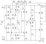
I will also here post my Class A preamplifier schematic, with Non feedback, folded back cascode coupling.
I would ask If someone have ideas to optimize the component values, so I can lower distortion or make some sound improvement?
The PSU will be a look a like LCaudio Shunt reg with (PSU will later be +-20V) outputimpedance at 0.01R from DC to 400Khz.
About decoupling, what I decouple the outputstage with 10uF and inputstage with 220nF?
And what if I use a super jung regulator?
Best regards
Kim
Hello
I will also here post my Class A preamplifier schematic, with Non feedback, folded back cascode coupling.
I would ask If someone have ideas to optimize the component values, so I can lower distortion or make some sound improvement?
The PSU will be a look a like LCaudio Shunt reg with (PSU will later be +-20V) outputimpedance at 0.01R from DC to 400Khz.
About decoupling, what I decouple the outputstage with 10uF and inputstage with 220nF?
And what if I use a super jung regulator?
Best regards
Kim
Attachments
thanks Kimschips.
I have been out of the industry for a few years but am preparing a comeback with a 150W Nch monoblock on spec.
I don't have a copy on hand and would need a schematic drawing pkg to generate it but it was a symmetrical FET input (2SK170/J74 Vgs matched) with complementary TR folded cascode LED biased and EF output in a x10 feedback loop with servo. Simple, nice bits and remote with motorised alps vol. The market loved it.
The amp that won with it started life as a no global feedback company design with comp bip front end, cascode Vas and MJ15003/4 - sounded awful. I tricked it up with comp FET front end applied global feedback and finessed the compensation for much better 20K THD. Absolutely transformed. 2x200W from memory.
regarding your design - I have a great pref for sym FET input with the balance R no CCS. I don't see the need for the 2 stage output. The loadings light enough. My opinion.
- Status
- This old topic is closed. If you want to reopen this topic, contact a moderator using the "Report Post" button.
- Home
- Amplifiers
- Solid State
- Symmetrical folded cascode.