Peter Daniel said:Here it is. Worth noticing is additional shielding plate between channels, something you never see on Elma's.
Thanks. Have you ever seen such a switch IRL??
Magura
")
Regarding the copper plate, the thinner gauge allows also for better flexibility and contact is improved if the flatness isn't perfect. That would be much harder to achieve with thicker plate.
Well yes, but doing so would counteract the very reason for putting it there in the first place!
/Magnus
Swedish Chef said:
Well yes, but doing so would counteract the very reason for putting it there in the first place!
/Magnus
How do you know that? Did you do any tests and have a proof for your claim?
Magura said:
Thanks. Have you ever seen such a switch IRL??
Magura
I didn't see the exact ones, nor lates Shallco, but I have some other, similar switchers.
Attachments
How do you know that? Did you do any tests and have a proof for your claim?
No. But let's look at what is happening here.
First, lets view the case where the junction resistance between the alu heat sink and the copper plate is infinite. No matter how low the thermal resistance of the copper plate (or any other material for that matter) is or how thick it is, the total resistance will be much larger (infinite) than just using an alu heat sink.
On the other end we have the case where the junction resistance is zero, i.e. a perfect thermal junction. In this case putting any material that has a lower thermal resistance than aluminium (copper has about one-half of that of aluminium) would be beneficial, regardless of thickness.
Now, in practice we will end up with a junction thermal resistance that is between those extremes, that is with a finite value. For any such given value there will be a corresponding thickness of the copper plate (i.e. a reduction in thermal resistance compared to aluminium) that cancels the resistance of the junction, that is the net effect compared to just using aluminium is zero. Increasing the plate thickness above that value (lowering resistance in the plane paralell to the plate) will improve heat transfer compared to aluminium. Decreasing it will make heat transfer worse.
Now, neither you nor I know the exact values here, we just have gut feelings about the thickness. Only careful modeling and real world experiments would tell.
My point is that you seem to believe that just putting copper there regardless of thickness would be beneficial. I say that that is not the case.
Then there are other factors for a practical implementation. Getting a low-resistance junction is difficult. And the different thermal expansion coefficients of copper and aluminium can create great mechanical stresses on a tight junction. There are numerous other complications although not all of them are significant for audio. Total weight is one of them - critical in pro audio but a non-issue in home audio.
Cheers
/Magnus
Swedish Chef said:
My point is that you seem to believe that just putting copper there regardless of thickness would be beneficial. I say that that is not the case.
If I believe in anything here, it would be the ingenuity of Denon engineers. I don't have any precized POV on that matter as I didn't perform any tests. However, it seems to me that thinner plate is better as it doesn't store the heat, but rather spreads it and quickly release it to aluminum heatsink.
As to the thickness of that plate, it's pretty easy to figure it out from a picture; it's definitely less than 2mm.
I only believe in ingenuity of Denon engineers.
Well, for purely technical issues I don't. For financial and marketing issues I do.
As to the thickness of that plate, it's pretty easy to figure it out from a picture; it's definitely less than 2mm.
For the first time we seem to agree!
That plate looks to me to be something in the vicinity of 1mm. That's what made me skeptic in the first place! But maybe that's enough, I don't know./Magnus
Yes, my guess would be around 1.5mm.
I also don't think that this is much of a marketing issue, as people who can afford such stuff usually don't have much clue about mechanical/materials concepts, so this wouldn't impress them, especially if nothing is printed about it. Also, financially it wouldn't be worth to introduce it just for the looks.
Those who like to build equipment, definitely look at this as something interesting and worth consideration.
Well, if I decide to build one more real man's amp, I might give it a try.
PS: As an interesting insight, most of you must have seen those copper looking angles, plates and screws in some upper level Japanese stereos. Well those are not made out of copper, but a regular magnetic material is plated in this color. Makes me wonder why, maybe for corosion protection?
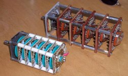
Peter's "switch 1" photo from the Denon is a Seiden. Luxman also uses these in some of their upper preamp models. The resistors are Riken RMGs (likewise used by Luxman), and found inside some Sony products.
The Seiden has a better tactile feel than a Tech-Lab or even Shallco (and is far more dependable than a Tech-Lab), but is quite large and heavy. The main reason why I don't use the Seidens is that in recent years the company has been unwilling to manufacture customized switches (I believe that they have lost key engineering staff).
BTW, the power supply of the Denon power amp (at least the PS for the output stage) utilized synchronous rectification (also using those UHC MOSFETs), which is unusual in audio amplifiers.
regards, jonathan carr
Swedish Chef said:
Now, neither you nor I know the exact values here, we just have gut feelings about the thickness. Only careful modeling and real world experiments would tell.
My point is that you seem to believe that just putting copper there regardless of thickness would be beneficial. I say that that is not the case.
For a TO-247 the "magic" number is a 10*50*100mm copper bar, with those dimensions the benefit is obvious. This is proven by real life setups. I usually go for more than that, but that's only because most heatsinks are so incredibly skimpy that you can benefit from it, if not for that there would not be any significant benefit, as the heat would never reach the edges of the copper.
As for the other drawbacks you mention, I have never seen any of them in real life applications, though theoretically you're right.
Magura
Peter Daniel said:
How do you know that? Did you do any tests and have a proof for your claim?
I've made a load of tests with heatspreaders, it's waste of time and money if thinner than 5mm. At 5mm it breaks even.
Magura
Magura said:
I've made a load of tests with heatspreaders, it's waste of time and money if thinner than 5mm. At 5mm it breaks even.
Magura
Does that mean you actually built the amp with it? I didn't see anything yet
Peter Daniel said:
Does that mean you actually built the amp with it? I didn't see anything yet
Nope, it means that I've made test setups to make sure that my theory is working in real life. I have made test setups with copper from 2 mm to 15mm and from 400mm2 to 10.000mm2 with TO-247 devices dissipating approx 50W.
Magura
Peter Daniel said:As to the copper, I would probably be using 1" square bars as spreaders when building Aleph X. I might do it soon, as I'm getting a bit bored with all those tiny amps
25mm wide bar is too little....or it will have to be 200mm long to make a significant benefit, that's a whole lot of copper and considering the copper price theese days, thats a very expensive (but impressive looking) solution.
According to my tests you don't gain much by making the heatspreader more than 12mm thick.
Magura
Well, it happens that I already have like 6 ft of that, so there is no other choice but to use it.
As to the impressive looking part, I've seen things that are much more impresive than that, like Cardas posts for instance.
The reason for 1" square is not looks, but structural convenience. BTW, it will be 11" long (I guess it's a bit more than 200mm)
As to the impressive looking part, I've seen things that are much more impresive than that, like Cardas posts for instance.
The reason for 1" square is not looks, but structural convenience. BTW, it will be 11" long (I guess it's a bit more than 200mm)
Peter,
Back in the day (I hate to admit it, but back in the mid 70's) I used to design solid HF Power Amps. I used Motorola RF power transistors and Motorola had recommended 1/4" copper plate between the heatsink and their RF power transistors to spread the heat out. Their applications engineers have always felt getting the heat away from the transistor by spreading it out over the whole heatsink was very important in keeping the junction temperature down. I guess a good indication of this is that if you touch an aluminum heatsink in operation you will find that the heat being dissipated is not even. The sink temperature is much cooler away from the transistors, Spreading the heat out allows the aluminum sink to dissipate heat more evenly and efficiently. As I understand, and I could be wrong (as I have not designed anything in a long while as I sell RF and Microwave test equipment for a living now), that copper is not as good of a heat dissipator as aluminum but is better at spreading the heat over a broader surface area making the combination of an aluminum sink and copper spreader optimal for conventional heat dissipation.
Back in the day (I hate to admit it, but back in the mid 70's) I used to design solid HF Power Amps. I used Motorola RF power transistors and Motorola had recommended 1/4" copper plate between the heatsink and their RF power transistors to spread the heat out. Their applications engineers have always felt getting the heat away from the transistor by spreading it out over the whole heatsink was very important in keeping the junction temperature down. I guess a good indication of this is that if you touch an aluminum heatsink in operation you will find that the heat being dissipated is not even. The sink temperature is much cooler away from the transistors, Spreading the heat out allows the aluminum sink to dissipate heat more evenly and efficiently. As I understand, and I could be wrong (as I have not designed anything in a long while as I sell RF and Microwave test equipment for a living now), that copper is not as good of a heat dissipator as aluminum but is better at spreading the heat over a broader surface area making the combination of an aluminum sink and copper spreader optimal for conventional heat dissipation.
that copper is not as good of a heat dissipator as aluminum but is better at spreading the heat
Hi Kilowattski,
Copper is a better conductor of heat than aluminum. So it spreads the heat more uniformly than aluminum for a specified thickness of material. Once you get to a large section with uniform heat throughput , you can use an aluminum sink with fins to dissipate the heat better than a flat plate ( more surface area).
The final section is aluminum because of cost . For the same reason the spreader should be only as thick as needed to cut down on copper cost. You can't use copper for the full heatsink mainly because of its cost -- in audio applications.
You will find copper heat spreaders on aluminum and stainless steel cook ware. The famous "copper bottom" cooking pots and pans! It does the same job.
Cheers.
Magura,
excellent of you to share your findings! That was exactly the hard data I was looking for here. Have you any secret bag of tricks for making the alu/copper junction as good as possible, or do you just sand them down and apply thermal grease? How about screw tightening arrangements, do you just run the M3's for the TO-247's all the way through or do you use lots of complementary screws?
Cheers
/Magnus
excellent of you to share your findings!
That was exactly the hard data I was looking for here. Have you any secret bag of tricks for making the alu/copper junction as good as possible, or do you just sand them down and apply thermal grease? How about screw tightening arrangements, do you just run the M3's for the TO-247's all the way through or do you use lots of complementary screws?Cheers
/Magnus
- Status
- This old topic is closed. If you want to reopen this topic, contact a moderator using the "Report Post" button.
- Home
- Amplifiers
- Solid State
- Ultra High Current Mosfets from Hitachi