Hi all,
I have read many interesting threads while lurking here, but this is my first post. I am thinking of repairing an SAE 2200 amp that I bought recently, and I'd like to know if anyone is willing to check my diagnostics and provide pointers. My eventual goal is to use the case and power supply to build a "Leach" amp, but I thought I might try repairing the output stage first for the experience. My poking and prodding has yielded the following:
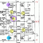
On one channel, the 2 output transistors and previous 2 (VA stage?) transistors are dead shorts, and the 62ohm resistor is open (yellow).
On the other channel (working, I was told, but I have not checked), one of the 10ohm resistors is open (blue).
The other 10 and 62ohm resistors (in purple if not otherwise colored) are looking rather scorched, but test fine. The 200pF capacitors nearby are scorched as well, apparently from being close to the resistors.
My questions are: Does this appear to be a typical "blown" output stage from some user abuse? If so, I might expect it to not blow again after repair. Are there any other parts I should look closely at?
I plan to replace to 4 transistors, and all the suspicious resistors and capacitors.
Finally, At wardsweb.com I found a part conversion table. For SAE 8 and 9, it lists easily obtainable motorola parts, but lists one NPN and one PNP for each type. I assume I should follow the schematic and get a PNP for SAE8 and NPN for SAE9.
I have not found the motorola replacement for the other transistors (listed as MJW21192/91), but I did find the set MJF122/27, which seem to have similar specs (i.e. 100v, 5A TO220). Would there be any pitfalls to using these parts?
I did not pay very much for the amp, so I'm willing to experiment. I'd rather not blow too many output transistors, though, if I can help it!
Thanks very much for any assistance.
Cheers, Dan
Attachments
I should replace all the coloured parts, and check the other transistors of the prestage (isn't shown on the picture).
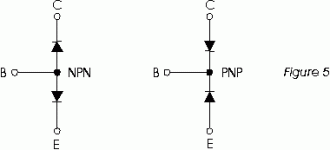
If you have a multimeter with a diode tester you have to measure a diode between the base and the emitter, and between the collector and the base, if your multimeter detects a short circuit (beep) or your multimeter cannot detect a diode the transistor must be replaced.
Try if the other channel still works, it's always easier to repair something if you can compare with a working example ;-)
best regards,
HB.
Attachments
Doh!
Thanks Mr. Pass,
I was wondering about that last night as well - they don't work that way, do they!
I double checked the parts list, and the parts are identified as you said, opposite of what is drawn and written on the schematic.
It's interesting, because apparently this schematic is official SAE work. I downloaded it from wardsweb.com as well.
Cheers, Dan
Just in case anyone is interested,
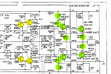
I was looking at my colored schematic, and I just noticed that all of the bad parts form a circuit from +V to -V, so when one transistor went, it must have sent an awful surge through that circuit, burning all the parts until one of them failed open. Probably all the experienced amp folks knew this all along.
This makes me think that the 0.2ohm resistors in the output stage are also fried. I was hoping not to get into that board because it is mounted upside down to the heat sink using the soldered output transistors. I'll have to remove them all...
I'm having a lot of fun with this and I haven't even replaced one resistor yet!
CHeers, Dan
yep, you're right!
when one output transistor is short-circuited when the other starts to conduct the fireworks begin
just another tip: look at the solderside of the pcb and search for brown coloured zones; this way you can find out which components went very hot and are probably toasted anyway.
HB.
when one output transistor is short-circuited when the other starts to conduct the fireworks begin
just another tip: look at the solderside of the pcb and search for brown coloured zones; this way you can find out which components went very hot and are probably toasted anyway.
HB.
Cool
So I'll be replacing all the components colored in green in the blown channel, and looking closely at the transistors in yellow. If there's a problem there, I'll also look at their associated passive components. It appears that in that stage of the amp, the transistors are pretty well protected from excess current, but on the other hand, they are pretty small devices too.
Thanks for all your help,
Dan
Attachments
<shrug>
I don't know, it was like this when I bought it. It is rather dusty inside and comes from a smoker's house, so there may be some contamination between some traces. From the overall look of it, it was not very well taken care of, and was driven hard.
From my perusal of the SAE yahoo group archives, these amps seem to have a tendency to blow output stages.
I checked in at the yahoo forum to see if I should even attempt repair, or save the guts for a collector who might want to repair their own amp.
I just want the case and power supply.
Cheers, Dan
SAE2200 repair
Hi,
You should also check the diodes in the protection circuit as well as the protection transistors. And also check the 10 Ohm resistors in the powersupply line.
I am missing the quiescent bias circuit in the schematic. It usually blows up too if the outputtransistors die.

Hi,
You should also check the diodes in the protection circuit as well as the protection transistors. And also check the 10 Ohm resistors in the powersupply line.
I am missing the quiescent bias circuit in the schematic. It usually blows up too if the outputtransistors die.
oy
Thanks Elso,
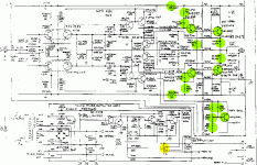
So now we have more components in green that need to be replaced or seriously scrutinized. I beleive I have identified the bias circuit in the lower right.
The only protection device I have found is a speaker relay (yellow). Am I missing something?
This may turn out to be more trouble/cost than it is worth in the end!
Sorry about the schematic. I had to shrink it so much it is illegible, but hopefully you can still see the general plan.
Cheers, Dan
Attachments
* * * * WARNING! * * * *
Be very careful. Is this a device that came with your fireplace fan?
2 things you will need to check.
1) Can you draw enough current through it?
2) How does this device lower the voltage? Does it use a true variable transformer? Is it a triac type device, like what they put in the cheap light dimmers? If you can open it up and see somthing that looks like a transistor (Typicaly a TO-220 package) you shouldn't use it.
Regards,
Aud_Mot
No worries
Thanks for your concern!
This really is a variac. It weighs about 30# and I think it is rated for about 20 amps. I plug it into the wall and then plug the fan into it so I can run the fan slowly and cut the noise.
It is rather old and "industrial" looking (green paint and all that), with about a 4 inch knob on top. I can guarantee there are no wimpy transistors in there.
Cheers, Dan
- Status
- This old topic is closed. If you want to reopen this topic, contact a moderator using the "Report Post" button.
- Home
- Amplifiers
- Solid State
- Repairing SAE 2200


