ok, well i have just finished building two of these suckers..
I managed to build them both into a 3U rack case too
so far i have only tested it out with 4R subwoofers and the only sub that could handle even half teh power was a phenix gold 1000W 15". anyway, that doesnt say much..
I have a question, how could i put an attenuator pot on the input as a volume control? After reading so much debate on the gainclones im no longer sure i can use a pot without upsetting the frequency response as the intended use is for full range studio monitors
I'll post some pics and full range impressions when i can
here is the schematic
http://us1.webpublications.com.au/static/images/articles/i1005/100503_15mg.jpg

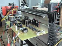
I have just finished to build one, with only half of the power transistors. And i made some tortures to this great amplifier. I plug it to my electrostatic loudspeaker prototype, about 0.5 ohms of impedance... I have plenty of power and audio spectre is excellent maybe a little too brite. But this can be corrected with a simple equaliser circuit.
What amazed me is the high PSRR when there is no signal input there is absolutly no hiss or hum hearable even the ear stuck to the speaker.
And i have just 5400uF on each side of the dual supply polarities.
There is still some errors in the construction details, like the output self
6.8uH. In the text they says use a 3 meters long 1mm diameter copper wire... In reality it's 1 meter long. You have to use 0.5 inch diameter inside core make about 6 turns each layer (that make about 0.25 inch of thickness) and you repeat for about 3 layers, +- 21 turns. It's difficult to layers rigid wire like that it tends to spread between previous layers, so i put a tape on top of each layer. Voila!
Here is a photo of my prototype:
Attachments
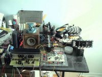
I think that the electromagnetic canceling topology
greatly improve the quality of this amplifier. I've compare
this design to some others and found that performance
is very high for a not so complex circuit. I encourage even
beginners to build this Studio350. Just make shure to follow
first testing instructions very well, because quiescent current
can destroy your complete high power transistors in split second...
A photo of my loudspeaker protype.
Attachments
Studio 350
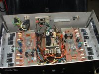
I've built two versions of this excellent amplifier, one for subwoofer purposes the other as a regular amplifier.
I'm very happy with the sound quality and simplicity of construction and above all with the setup after the construction.
No noise, no hum, a very quiet amplifier.
I think that after the SC480 this amplifier satisfies my needs
either as a subwoofer amp or a full range one.
Attachments

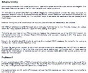
To TOHEED Setup and Testing.
Hi TOHEED i search in my papers and i found what you wanted, the
setup and testing procedures.
I scan my paper so forgive me the low resolution but it's readable.
Hope you found this usefull and you have succes in building that high performance amplifier. If you have further questions dont hesitate to contact me.
So here it is as a picture.
Bye
Mandrake5")
Hi TOHEED i search in my papers and i found what you wanted, the
setup and testing procedures.
I scan my paper so forgive me the low resolution but it's readable.
Hope you found this usefull and you have succes in building that high performance amplifier. If you have further questions dont hesitate to contact me.
So here it is as a picture.
Bye
Mandrake5
Oupps the picture was missing!!!
Here is the picture with setup instructions.
Here is the picture with setup instructions.
An externally hosted image should be here but it was not working when we last tested it.
Attachments
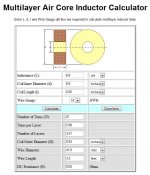
How to make the 6.8uH inductor.
Hi Toheed,
First in the Post number 5, i explained exactly the procedure...
But i give you the calculations on how i figured out the the original procedure was wrong...
What you have to get is 18AWG or 1mm diameter solid enameled copper wire (about 1 meter long). Some electrical tape or fishing line as a mean on holding everything in place, and maybe some varnish for dipping the finished multi layer air coil, voila!!!
Bye
Mandrake5
Attachments
About the fishing line..
Again for Toheed
What i mean about holding everything in place after you've make the coil is, you take the coil that you give a donut shape, you take a lenght of fishing line and tie a loop around the donut. with the fishing line you makes some Marline hitch knots around the donut until you reach the first tie knot, you tie the end to that knot. Try to make you coil lead at 180 degres of the donut, you can secure the 2 leads with the knots.
You have the peel or sand the enamel from the leads in order to solder them to the pcb. And for the finishing touch you can dip the donut in clear varnish (dont varnish the leads) and let dry it for a super look.
Oh i read you're mind, ???? "What is a Marline Hitch Knot ???"
Well, well, i use it for a long time without knowing the "Name" of it, so i make some researchs just for you.
Here it is;
Attachments

To Stcboy if your are really interrested...
You'll buy this article here for the price of only one power transistor...
Online access to the issue in question.
And you might find interresting browsing other articles too.
I am not advertissing but suggesting an interresting link.
You'll buy this article here for the price of only one power transistor...
Online access to the issue in question.
And you might find interresting browsing other articles too.
I am not advertissing but suggesting an interresting link.
- Status
- This old topic is closed. If you want to reopen this topic, contact a moderator using the "Report Post" button.
- Home
- Amplifiers
- Solid State
- Jaycar/Silicon chip Studio 350 opinions?