Hi All
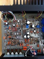
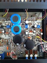
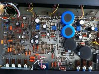
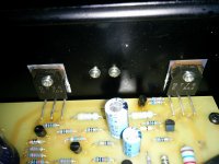
After a long time, finally some pics of my A28 with brand new caps")
Many thanks to Nikolay for the 2 blue BC caps 10000uF/40V, and to Patrick for his helping hand with Mouser order. Nice to see concerned DIYer's
I've encountered some troubles due to caps size and "extended" existing holes for them to fit in.
Be carefull when you desolder components, PCB traces are IMHO very "weak".
The amp is sounding fine, but the right channel is much warmer than the left.
Could someone point me to what to check and "howto"
Thanks for your help
Regards
Phil
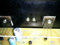
After a long time, finally some pics of my A28 with brand new caps
Many thanks to Nikolay for the 2 blue BC caps 10000uF/40V, and to Patrick for his helping hand with Mouser order. Nice to see concerned DIYer's
I've encountered some troubles due to caps size and "extended" existing holes for them to fit in.
Be carefull when you desolder components, PCB traces are IMHO very "weak".
The amp is sounding fine, but the right channel is much warmer than the left.
Could someone point me to what to check and "howto"
Thanks for your help
Regards
Phil
Attachments
Hello Phil,
The temperature difference is due to improper biasing of the output stages. You have to adjust the 4.7 k blue trimmer, for each channel, until you can read approximately 300 mA on your ammeter that should be connected to the fuse holder contacts. Do not forget to remove the fuse for this measurement. Unless you have two ammeters, do one channel at a time. Make sure you let the amp warm-up for at least an hour and readjust until it stabilizes. When this is done measure the voltage between the emitters of each pair of output transistors to confirm it is approximately the same.
Good luck!
Michel
Lovely amplifier. Glad I could help.
Regards,
Nikolay
Class A magic sound .
Question a Michel
Montréal, 2013-08-02
Bonjour Michel,
Je demeure sur la rive sud de Montreal et je suis a la recherche d'information concernant un Sugden P28B. J'ai besoin de faire vérifier l'ampli. Est-ce que tu fait cela ? connais-tu un endroit fiable ? Peux-t-on communiquer ? tu peux m'écrire a mon email y_lefebvre@hotmail.com
Hi Michel, i live in the south shore of Montreal. I search information about a sugden P28B. i would like to bring my amp for a check up. do you do this ? do you know a good place ? can we communicate ? you can send me an email to y_lefebvre@hotmail.com.
Merci pour ton aide.
Yves
Smokey Mountains
Hello, replying to this thread.
I have bought a pair of sugden p28, both identical rear heatsink gold text on front.
They have been standing for 10 years unused.
Some work has been done to them, a note says that its rewired to go mono.
When connected i got some smoke coming out of one amp, and also no sound.
Evidently some component blew, so i opened and a resistor between the 2 leftside transistors the one furthest in towards the sink was burned.
When i measure the transistors i get 1st 4 volts 2nd 0 volts 3/4rd 0,62 volts.
And over the fusesholders 80ma.
Also when i connected the preamp something broke (in the preamp), feels like an shortcircuit?
So i wonder if some nice soul could send me schematics so i can get some spares for the amp.
And if someone have an idea about what i should look for or even had a similar
problem please tell.
Im going mono.....
my adress:
a r o n @ g r i n d v i k . n u
Hi David .... I don't quite understand what you mean. Could you clarify this explanation ,please ?
Other technicians on a French forum certify that the 20W Class A indicated by the manufacturer are impossible in this assembly with only 300mA bias. Should be at least 1 A... What is your opinion?
Regards . Dom
Other technicians on a French forum certify that the 20W Class A indicated by the manufacturer are impossible in this assembly with only 300mA bias. Should be at least 1 A... What is your opinion?
Regards . Dom
There are complex circuits that control the output devices in individual feedback loops, aiming for a square law transconductance. Quiescent of 300mA in each device becomes 1.2A and 0mA rather than 600mA and 0mA at the limit of class A working. Apart from the complexity, this also cause the output stage to generate 3rd harmonic distortion in the class A region.
Another possibility would be to control the two output devices so that the product of the two currents (Itr1 x Itr2) is a constant. This would mean that no matter how high the current was in one device, the other would never completely cut off. This means that the output is always class A, but generates plenty of odd order distortion
Sugden don't do any of these tricks

Did Sugden themselves actually claim Class A?
There is confusion in the press with the A21 mk1 and 2 and A41 which had moderate Class A ranges (see The A21 Series 2)
There is confusion in the press with the A21 mk1 and 2 and A41 which had moderate Class A ranges (see The A21 Series 2)
Sugden A28II - need help
I am struggling with my next steps to try in order to fix the following problem. I was able to adjust idle current at 300 mA and set midpoint to 31.5 volts but I notice that I have some DC voltage on the speaker outputs.
When I turn the power on, the DC ramps up to 8 volts then after a minute it's down to around 10 mV. When I turn the amp off, the DC ramps back up again to around 10 volts and slowly trickles back down to o volts.
Also I notice a hum when I increase the volume with no audio playing in the aux input. I use an ipod in the auxiliary.
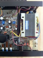
The person that gave me the amp told me that he had some capacitors changed. I am including a couple of photos as visually I cannot tell if they are original caps or not.
Can anyone pitch in some ideas to check ? I attached preamp and amp circuit.


I am struggling with my next steps to try in order to fix the following problem. I was able to adjust idle current at 300 mA and set midpoint to 31.5 volts but I notice that I have some DC voltage on the speaker outputs.
When I turn the power on, the DC ramps up to 8 volts then after a minute it's down to around 10 mV. When I turn the amp off, the DC ramps back up again to around 10 volts and slowly trickles back down to o volts.
Also I notice a hum when I increase the volume with no audio playing in the aux input. I use an ipod in the auxiliary.
The person that gave me the amp told me that he had some capacitors changed. I am including a couple of photos as visually I cannot tell if they are original caps or not.
Can anyone pitch in some ideas to check ? I attached preamp and amp circuit.
That's a good point ! I notice in the schematics a 1R0 and 220 nF. Should I be replacing the 1K2 with these components ?
Is 1R0 equal to 10 ohms or 1 ohms ? Is the capacitor an electrolyte with polarity ?
The previous owner told me that an audio shop changed the speaker terminals, so they most likely did not replace with the right resistors.

Is 1R0 equal to 10 ohms or 1 ohms ? Is the capacitor an electrolyte with polarity ?
The previous owner told me that an audio shop changed the speaker terminals, so they most likely did not replace with the right resistors.
Last edited:
- Home
- Amplifiers
- Solid State
- Sugden P28