Hi again
Some poeple may ask why I tend to show bizzare and stupid topologies.
Are you fed up??
I'm just bored with always the same topologies again and again...
What I do is (pathetic?) trial to find some new ways
so I show you thoughts that came through my mind...
patience please....
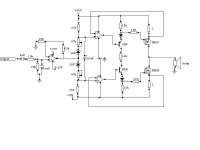
This one uses 3 integrated OPAMPS and 3 short feedbackloops.
Values aren't crucial - take care to topology
Looking forward to comments
(schematic attached)
Some poeple may ask why I tend to show bizzare and stupid topologies.
Are you fed up??
I'm just bored with always the same topologies again and again...
What I do is (pathetic?) trial to find some new ways
so I show you thoughts that came through my mind...
patience please....
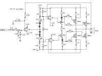
This one uses 3 integrated OPAMPS and 3 short feedbackloops.
Values aren't crucial - take care to topology
Looking forward to comments
(schematic attached)
Attachments
Why don't you get a Simulator program? LT Spice is free, from Linear Technology website. I haven't used that one, but I have a simulator. If I have an idea, I can draw it out, run the simulator, and see what happens. It really is a very good way of trying things out. You don't get the smoke that you get with a breadboard layout, and it will display all the operating conditions for you without the need for measurements. You would easily be able to try any topology you can think of.
darkfenriz said:
hi Tube_Dude
I don't get your point
what is CCS ?
Is a Constant Current Source...that mean that it will suplly the some current independent of the impedance of the load.
In simple terms your amp will have a output impedance of MOhms.
For to make your amp a normal voltage amp you must take the feedback from the output...
darkfenriz said:DEAR Tube_Dude
I thought that feedback loops taken from sources to the -input of opamps will do...
when one mosfet is open and the second closed there's huge current through the speaker and thus through the dren resistor..
much confusion....
Yes ...much confusion
With your feedback schema you are sensing the current through the load...then making a current amplifier.
There are a couple of threads about driving a 'speaker with a current amplifier, there are some advantages, but I don't think that you intended to design such a thing.
What about the crossover region between positive and negative output currents? would it give high crossover distortion?
I think a simulator would tell you a lot, if you split the design into sections and simulated each section independantly, you would see what each section does, with all the operating conditions, and then you would have a good idea how the whole thing would work.
- Status
- This old topic is closed. If you want to reopen this topic, contact a moderator using the "Report Post" button.
- Home
- Amplifiers
- Solid State
- Another out of this world topology