hi everyone!!
here I have a very simple push-pull project
what I inteded to avoid is classic push-pull topology which products
classic push-pull distortions.
in spite of good thd classic push-pull amp seems to make some ugly things.
let's consider the signal routing:
input signal->voltage amplification(+distortion)->
->freq. compensation(delay + dispersion)->output power(distortion again)->
->low boost in negative feedback i.e.cap to the ground
(huge delay and dispersion-it's 1st order)->back to VAS
so the distoted signal comes back to diffy stage dispersed and after some delay
maybe that's why in spite of good THD these amps make some 'sss' or 'bzzz' after
short impulses and non-feedback class A amps are often found better.
Here a trial of avoiding these problems.
I fear the thermal stability and some resistor values of attached amp.
I hope DC at output is going to be acceptable (am I naive??)
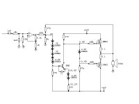
The main advantage of my project is its simplicity I believe.
3 transistors only with no reactive components within feedback
(a base to emitter cap is probably not nessesary-no need for frequency compensation
in an amp that simple, if I'm wrong this should be single picofarads).
just an idea...
what do you think???
cheers
Adam
here I have a very simple push-pull project
what I inteded to avoid is classic push-pull topology which products
classic push-pull distortions.
in spite of good thd classic push-pull amp seems to make some ugly things.
let's consider the signal routing:
input signal->voltage amplification(+distortion)->
->freq. compensation(delay + dispersion)->output power(distortion again)->
->low boost in negative feedback i.e.cap to the ground
(huge delay and dispersion-it's 1st order)->back to VAS
so the distoted signal comes back to diffy stage dispersed and after some delay
maybe that's why in spite of good THD these amps make some 'sss' or 'bzzz' after
short impulses and non-feedback class A amps are often found better.
Here a trial of avoiding these problems.
I fear the thermal stability and some resistor values of attached amp.
I hope DC at output is going to be acceptable (am I naive??)
The main advantage of my project is its simplicity I believe.
3 transistors only with no reactive components within feedback
(a base to emitter cap is probably not nessesary-no need for frequency compensation
in an amp that simple, if I'm wrong this should be single picofarads).
just an idea...
what do you think???
cheers
Adam
Attachments
hi !
I think, that many diodes might generate a lot of noise. Also it is
not the best idea to "mirror" voltages with a fixed voltage (~22v in your case)
This means, that the amp will only work correctly with exactly +/- 40volts.
So, when switching on/off it will generate hell of DC.
Typically the caps for frequency-compensation are between B-C.
AND, if you wanted to avoid any diffamp and typical pushpull, get
rid off the opamp, these use exactly what you wanted to avoid.
As its not inside the feedbackloop, it might not disturb.
BUT, keep on, it's really time for some new topology !
Mike
Perfect (passive only) differencing junction
One thing I like about it is the feedback resistor that goes to the summing junction carries a *perfect* representation of the output signal. This is not true in a diff amp equipped cct where the FB signal gets fed to the right-hand-side diff amp transistor base, and when it exits out the emitter to do it's feedback stuff it is no longer a perfect representation of what is happening at the amp output.
This is precisely the reason I think some people can hear a difference between inverting and non-inverting GainClones.
hallo MikeB
the OPAMP is low-power, very fast, and short-feedback, so the high-end one isn't a problem for me
but concerning DC you're absolutely right
the rails may be lower even at full power by several volts
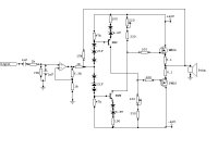
Maybe this is gonna solve the problem- I mirrored the whole stuff so only thing to change with different rail voltage is bias
What do you think??
the OPAMP is low-power, very fast, and short-feedback, so the high-end one isn't a problem for me
but concerning DC you're absolutely right
the rails may be lower even at full power by several volts
Maybe this is gonna solve the problem- I mirrored the whole stuff so only thing to change with different rail voltage is bias
What do you think??
Attachments
darkfenriz said:hallo MikeB
the OPAMP is low-power, very fast, and short-feedback, so the high-end one isn't a problem for me
but concerning DC you're absolutely right
the rails may be lower even at full power by several volts
Maybe this is gonna solve the problem- I mirrored the whole stuff so only thing to change with different rail voltage is bias
What do you think??
Yes, the DC-problem should be gone, but biasing is still very unsteady.
Means, 1volt more supply, the amp gonna smoke, 1volt less, it stops working...
Mike
- Status
- This old topic is closed. If you want to reopen this topic, contact a moderator using the "Report Post" button.