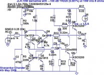
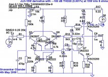
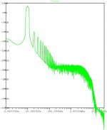
A long bump up - here's my derivative of the JLH Class-A using commodity Japanese devices and a very high gain LTP input stage. It simulates with THD20 of ~ -100 dB (H2 ~= H3) at 16W into 8 ohms, and ~-115 dB (H2 >> H3) at 1W into 8 ohms.
(A simplified version, using only 6 transistors, omits the current mirror Q3-Q5, Q4, and associated resistors, and substitutes them with a single 6.8k resistor to ground, similar to the classic JLH. It simulates with ~20 dB higher distortion, which may still be acceptable).
(A simplified version, using only 6 transistors, omits the current mirror Q3-Q5, Q4, and associated resistors, and substitutes them with a single 6.8k resistor to ground, similar to the classic JLH. It simulates with ~20 dB higher distortion, which may still be acceptable).
Attachments
linuxguru said:A long bump up - here's my derivative of the JLH Class-A using commodity Japanese devices and a very high gain LTP input stage. It simulates with THD20 of ~ -100 dB (H2 ~= H3) at 16W into 8 ohms, and ~-115 dB (H2 >> H3) at 1W into 8 ohms.
(A simplified version, using only 6 transistors, omits the current mirror Q3-Q5, Q4, and associated resistors, and substitutes them with a single 6.8k resistor to ground, similar to the classic JLH. It simulates with ~20 dB higher distortion, which may still be acceptable).
I've been routinely baffled by the THD-20 figures you are getting from simulations of relatively basic circuits. In most cases they look to me to be, in part, the product of totally unrealistic frequency compensation schemes that provide heaps of loop gain at 20kHz but would never work in real life due to next to zero phase margin.
I figured the same for this one, so I simmed it myself just to satisfy my own curiosity, using Andy C’s NPN RET model for the output pair.
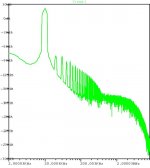
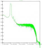
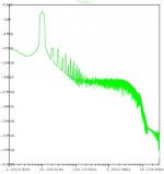
As expected it’s an oscillator (no amount of tweaking the compensation scheme used can fix it) , with THD-20 at only 1W into 8 ohms being 0.078%.
Attachments
> As expected it’s an oscillator (no amount of tweaking the compensation scheme used can fix it) , with THD-20 at only 1W into 8 ohms being 0.078%.
It has a lot of open-loop gain, so it's reasonable to expect that it is at the edge of stability and could oscillate with a different small-signal transistor models (2n2222/2n2907 in your case).
I'll try those two devices in due course, but I anticipate no problems in stabilizing it in the simulation with minor changes to the compensation components C5, C7 and R13 alone. In the worst case, a bit of emitter degeneration in the input LTP should fix things.
Whether the sim model is realistic enough to be able to build a real amp that is stable and has good sonics is another question. As I've stated earlier, I use the sim model only as a starting point for experimentation, and this one is no exception.
-Siva
linuxguru said:[BWhether the sim model is realistic enough to be able to build a real amp that is stable and has good sonics is another question.
Well in most cases there is no real reason why it shouldn’t be and if the simulated design is on the edge of stability, then we have an obvious answer for that question.
One of the most powerful features of SPICE for amplifier design is that it allows detailed analysis of open loop characteristics and closed loop stability. The goal of testing an experimental NFB design in SPICE should be to get best linearity with acceptable phase margin, not the lowest THD-20 with nearly zero phase margin.
The former typically relates to something that can be successfully built and commissioned, the latter typically does not.
Cheers,
Glen
Glen, I plugged in the 2n2222/2n2907, with no other changes in my sim model, and it oscillated in much the same way as yours did - obviously it was at the edge of stability.
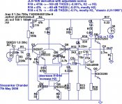
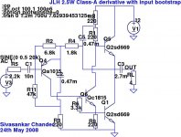
A quick inspection revealed that using the 2n2222 as the phase-splitter/driver in a JLH is a misapplication - it doesn't have sufficient Vceo (30V only) for 36V rails in a JLH, and Cob is probably too non-linear. Typically, one uses a fast medium-voltage driver like a 2sc4793, 2sc5171, 2sc3421 or 2sd669 here to drive a 2sc5200 pair. A sim revealed that using the 2n2222/2n2907 for the six transistors in the LTP section, while retaining the 2sd669 as the phase-splitter, and no other changes, gave a stable circuit. Similarly, with the 2sc5171. But a bd139, 2n2222 or 2sc4793 as the phase splitter led to instability.
Anyway, the fix was easy - a small Cdom of 22-27pF between base-collector of the phase-splitter tamed the instability with the 2n2222, and it remained stable with the 2sd669, 2sc5171, and bd139 as well. The mod is shown below - an added bonus is that the sonics of the design with the 2n2222 splitter (ignoring Vceo for the moment) are superior in the sim to that of the 2sd669.
At 1W output, the 2n2222/2n2907/2sd669 combo sims with H2 ~= -113 dB, H3 ~= -130dB. An identical circuit with the 2n2222 sims with H2 ~= -110 dB, H3 ~= -135dB.
So I'll retain the Cdom, though of course the 2sd669 as the splitter is the recommended device in practice (and doesn't require Cdom in the sim). Thanks for your corner case that helped uncover the lack of phase margin in the previous design.
Attachments
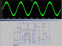
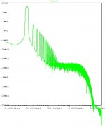
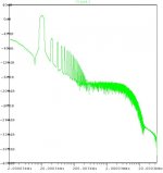
OK, I added the 27pF Miller cap to my simulation and now the design is stable with a steady sinewave input delivering 15W into 8 ohms. THD-20 is 0.002%
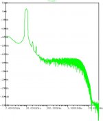
However, even with the 27pF miller cap the unity gain crossover frequency (unity loop gain) is still unrealistically high at 4.2MHz.
I added a pair of 43-ohm emitter degeneration resistors to the LTP to bring the crossover frequency down to a more realistic frequency of 1.5MHz.
I would be confident about being successful at implementing a real life version that is stable with this crossover frequency, however, as expected, the THD-20 has now risen considerably (to 0.024% at 15W into 8 ohms).
I think that is a reasonably realistic distortion figure for a refined amplifier using this type of output stage.
Cheers,
Glen
Another new wrinkle, along with a further set of tweaks - in the circuit below, the sonics (as well as THD) can be tuned by adjusting a single resistor, R18. If it's low, the H2 component is significant, but the THD is also higher - similar to the classic JLH1969. By increasing R18, it's possible to progressively lower the THD, but at the cost of decreasing the H2/H3 ratio.
In principle, it's possible to have a selector switch (or maybe a CD4066 quad-bilateral switch) to select the desired sonics from the front panel - say Classic JLH, Normal or Low-Distortion; or maybe even a log-potentiometer.
In principle, it's possible to have a selector switch (or maybe a CD4066 quad-bilateral switch) to select the desired sonics from the front panel - say Classic JLH, Normal or Low-Distortion; or maybe even a log-potentiometer.
Attachments
An idea for input bootstrapping on the original 4 transistor JLH topology follows - this is only a concept for simulation, although it could be built to deliver >2.5W into 4 ohms with a single +12v rail.
The main idea here is to increase the input impedance sufficiently to allow the use of a small input coupling capacitor, which could be high quality, e.g. styroflex or silver mica.
The main idea here is to increase the input impedance sufficiently to allow the use of a small input coupling capacitor, which could be high quality, e.g. styroflex or silver mica.
Attachments
- Status
- This old topic is closed. If you want to reopen this topic, contact a moderator using the "Report Post" button.
- Home
- Amplifiers
- Solid State
- Graham's Class A/JLH output