Originally posted this in analogue by mistake, mods feel free to delete if you wish.
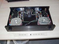
This is an amplifier I designed several years ago, its unusual in that it has an error correcting output stage based on Hawksfords topology. The PSU used T-Network capacitors from DNM see:
http://www.dnm.co.uk/capacitors.html#tnetwork
It is not really a project for the beginner, but if you persevere it does sound nice, a friend compared it to his Chord SPM1200 and thought it did not go as loud but that was is only criticism. Have fun!
Attachments
PSU schematic original files are ISIS/ARES readers are available from www.labcenter.co.uk
Attachments
IME chip amps sound OK for most purposes, but lack that finesse, bass slam and three dimensional imaging you get with a good discrete design. Basically I have not heard an amplifier costing less than 3000UKP sounding anywhere near as good as this design. Someone has reviewed in another forum, I will ask permission to post it here.
Russ
Russ
Error
Apologies there is an error in the original schematic, if anyone was wondering why the junction of C5 and D1 one did not go anywhere it goes to the junction of R15 R13 and Q9. The PCB is correct. Moral of story do not try and do any work with small children in the vicinity.
Apologies there is an error in the original schematic, if anyone was wondering why the junction of C5 and D1 one did not go anywhere it goes to the junction of R15 R13 and Q9. The PCB is correct. Moral of story do not try and do any work with small children in the vicinity.
Attachments
Russ, I'm last one, who need explanation about sound of this type amp ") , I say again, I like error correction ( my design is little bit more complicated, but in principle similar ). I'm using too dual monaural conception, but my devices inside are little bit less sloshed - it was joke . But remember, that most of guys here like much more simply design and when are talking about discrete design, they stoped thinking by six transistor quasicomplement .
, I say again, I like error correction ( my design is little bit more complicated, but in principle similar ). I'm using too dual monaural conception, but my devices inside are little bit less sloshed - it was joke . But remember, that most of guys here like much more simply design and when are talking about discrete design, they stoped thinking by six transistor quasicomplement .
, I say again, I like error correction ( my design is little bit more complicated, but in principle similar ). I'm using too dual monaural conception, but my devices inside are little bit less sloshed - it was joke . But remember, that most of guys here like much more simply design and when are talking about discrete design, they stoped thinking by six transistor quasicomplement .Re: Error
Hi Rusel,
Are you aware that you can auto-transfer a Proteus schematic diagram to the layout part, and be 100% sure that the layout corresponds with the diagram? Use Tools|Netlist to Ares or Alt-A. Manually updating the layout is very error prone.
BTW I guess you let the autorouter run the routing? I'm sure you can do much better than that!
Jan Didden
russel_h said:Apologies there is an error in the original schematic, if anyone was wondering why the junction of C5 and D1 one did not go anywhere it goes to the junction of R15 R13 and Q9. The PCB is correct. Moral of story do not try and do any work with small children in the vicinity.
Hi Rusel,
Are you aware that you can auto-transfer a Proteus schematic diagram to the layout part, and be 100% sure that the layout corresponds with the diagram? Use Tools|Netlist to Ares or Alt-A. Manually updating the layout is very error prone.
BTW I guess you let the autorouter run the routing? I'm sure you can do much better than that!
Jan Didden
Hi,
Hawksfords paper on error correcting is at:
http://www.essex.ac.uk/ese/research...6 Distortion correction, power amplifiers.pdf
or http://tinyurl.com/48lob if you get wrap round problems.
Hawksfords paper on error correcting is at:
http://www.essex.ac.uk/ese/research...6 Distortion correction, power amplifiers.pdf
or http://tinyurl.com/48lob if you get wrap round problems.
*Are you aware that you can auto-transfer a Proteus schematic diagram to the layout part, and be 100% sure that the layout corresponds with the diagram? Use Tools|Netlist to Ares or Alt-A. Manually updating the layout is very error prone.
BTW I guess you let the autorouter run the routing? I'm sure you can do much better than that!*
Yes I did, I just did not check it before submitting, not having changed it myself I did not think it necessary :-(. No I did not let the autorouter do the routing, primary aim was to get the earthing right rather than have the board look pretty. If I had access to proper board making facilities at the time it would have no doubt looked a lot neater. I have just had a hobby board done by www.pcb-pool.com and it is definately the way to go.
Cheers

russel_h said:.....a friend compared it to his Chord SPM1200 and thought it did not go as loud.....
All in the power supply mate, everything else being equal of course....
- Status
- This old topic is closed. If you want to reopen this topic, contact a moderator using the "Report Post" button.
- Home
- Amplifiers
- Solid State
- FET amplifier