x-pro: Very interesting ") Nice and simple design. And the rail loss is somewhat lower than the Citation 12 clone. In this design i would say something like 3.2 Volts on the first saturating rail, (the positive rail in this design). Pretty good!
Nice and simple design. And the rail loss is somewhat lower than the Citation 12 clone. In this design i would say something like 3.2 Volts on the first saturating rail, (the positive rail in this design). Pretty good!
Thijs: It seems that Q6 and Q7 are the pull-down current generator for the voltage amplifier stage (Q5).
Nice and simple design. And the rail loss is somewhat lower than the Citation 12 clone. In this design i would say something like 3.2 Volts on the first saturating rail, (the positive rail in this design). Pretty good!Thijs: It seems that Q6 and Q7 are the pull-down current generator for the voltage amplifier stage (Q5).
2 tschrama
yes, R6 provides some local feedback and makes VA more linear.
2 Lars Clausen
This configuration of the output stage is a pretty good follower - THD into 8 Ohm would be around 0.2% without the overall feedback with 70-100 mA idle current. R21 allows for a correct temperature compensation of the output devices. As you may see, there is no source resistors on the output devices.
If somebody would try to repeat this circuit - few comments:
1) It is useful to add a small coil in parallel with 1 Ohm resistor in series with the output after Zobel R23 C7 - say 10 turns of enamelled wire 1mm diameter on a 2 Watt resistor. In production this inductance was provided by wiring to the output sockets.
2) Q8 should be touching the heatsink close to Q11 and Q12, and these should be mounted using mika washers and good thermal compound. If you use silicon rubber washers than the output would blow sooner or later.
3) It would be advisable to increase the value of R22 to 0.47 Ohm 6W W/W and add another same value resistor as shown in the attached picture - this makes the output stage much more tolerant of short circuit condition.
Cheers
x-pro
Attachments
Hi x-pro,
I didn't forget Your amplifier. I will attach some schematics about my design. I already get lot of IRFP 250N, and IRF9630 as the driver. For the bias setting, I want use IRF9630 in the positon of Q9, and I ill increase the current up to 40-50mA for the 10 output devices.
I also planned to use some bootstrapping for the bias setting network to reduce the losses on the positive voltage swing.
I hope my ideas are good....
sajti
Sam: Sure! I will send as soon as i have the PCB's ready, and i'm sure it's stable, also in 500 Watts, with high capacitive load, high temperature and high frequency signals. All simultanously.
My own versions will be 500 Watts / 8Ohms with APT50M65 or IXYS equivalent. So i will sort of start with the high powered version, and work my way down to 300, 100 and (just for nexus ;-) ) 50 Watts.
My own versions will be 500 Watts / 8Ohms with APT50M65 or IXYS equivalent. So i will sort of start with the high powered version, and work my way down to 300, 100 and (just for nexus ;-) ) 50 Watts.
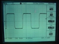
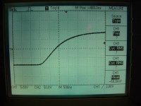
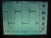
And last 10 kHz square wave with 8 Ohms resistive with 1 uF parallel load. The classic stability test.
There are no coils in series with the output, but it still maintains stability. This is due to the shift to local feedback at high frequencies.
The stability test was done at 8 W power, which is the worst case for this particular setup. At higher or lower powers, the ripples are smaller.
There are no coils in series with the output, but it still maintains stability. This is due to the shift to local feedback at high frequencies.
The stability test was done at 8 W power, which is the worst case for this particular setup. At higher or lower powers, the ripples are smaller.
Attachments
Hi Lars,
You are really making me interested. Could you send me a schematic to my personal email (t_schrama@hotmail.com)? Or maybe you could post a general topology of you circuit whithn out specific details?
Have you experienced any 'cross-conduction' ?
Best regards,
Thijs
You are really making me interested. Could you send me a schematic to my personal email (t_schrama@hotmail.com)? Or maybe you could post a general topology of you circuit whithn out specific details?
Have you experienced any 'cross-conduction' ?
Best regards,
Thijs
Thijs: As a matter fact i did:
With a normalized bias current of 33 mA i measured the following:
1 kHz: 33 mA
10 kHz: 37 mA
100 kHz: 56 mA
200 kHz: 60 mA
300 kHz: 71 mA
400 kHz: 94 mA
500 kHz: 145 mA
At these measurements i adjusted the input signal up, to maintain
full amplitude on the output, even when the gain starts to fall off above 330 kHz.
If i maintained a constant input signal, the bias + cross conduction actually falls off above 250 kHz, because the amplitude starts to slowly decrease at that frequency. So the max. bias + cross conduction is 65 mA. Nothing to worry about
IRF640N devices used in the above test.
A similar test performed with IRFP250N showed no significant difference in the result. (Surprisingly enough).
hi x-pro
I have a question about the creek 4330 amp.
the feedback looks very strange to me, I mean the integrating amp based on the opamps:
the input of the first opamp is an output of the whole amp. so the voltage swing is up to say +- 29V. isn't it to high for the opamp??
it seems the best way to burn it.
what is more, the integrator is very slow and may cause ocsilations I fear, how about a simple cap to the ground in 'conventional' feedback...
one more thing is input offset voltage of TL074 13mV
twice is 26mV-this may cause DC at the output...
do you share my fears???
darkfenriz said:hi x-pro
I have a question about the creek 4330 amp.
the feedback looks very strange to me, I mean the integrating amp based on the opamps:
the input of the first opamp is an output of the whole amp. so the voltage swing is up to say +- 29V. isn't it to high for the opamp??
it seems the best way to burn it.
what is more, the integrator is very slow and may cause ocsilations I fear, how about a simple cap to the ground in 'conventional' feedback...
one more thing is input offset voltage of TL074 13mV
twice is 26mV-this may cause DC at the output...
do you share my fears???
darkfenriz,
nothing to fear
. Main feedback loop is R10 and R9, giving closed loop gain of 44. Opamps create what is called "servo" loop, correcting for the DC on the output without using electrolytic capacitors in the signal path - considerably improving the sound quality. Integrator here is a first order network and can not cause oscillations. The input of the opamp even under a fault condition would not be damaged by few microamps current through 4.7 M resistor. 13 mV offset of TL074 would create a maximum 13 mV offset on the output (not 26, as only the offset of the first opamp is relevant) - perfectly acceptable figure. Usual level of the offset in production was from 3 to 10 mV.
No fears - many thousands of this amps were produced from 1997 till 2002 and still make their owners happy. I listen to one myself at home
x-pro
My N-Channel amplifier schematic (500 Watt / 1000 Watt version) is now drawn up.
For reasons mentioned earlier i can not post here in the forum, but
you can take a look here:
N-Channel Schematic
Lars
For reasons mentioned earlier i can not post here in the forum, but
you can take a look here:
N-Channel Schematic
Lars
- Status
- This old topic is closed. If you want to reopen this topic, contact a moderator using the "Report Post" button.
- Home
- Amplifiers
- Solid State
- N-Channel mosfet amplifier schematic needed