I'm aiming at making good sounding power amp. So, I decided that I have to know what kind of sound every different transistor make.
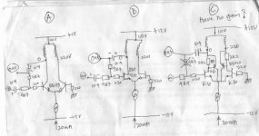
The idea is to make buffer (gain=1) with different kind of transistor. Because I'm using low rail (+/-15V), I use power transformer's primary (0-110V-220V) as load.
The configuration is differential preamp, but with different kind of transistor. With input R=4k7 and feedback R=4k7, I can get AC gain=1. I put A/B switch, so I can switch the signal feeding through the preamp or bypassed (not thru preamp), so I can hear what difference it makes compared with original signal.
A is bipolar (BD139). Compared to bypassed, it gives less detail, the sound is so-so.----having voltage gain.
B is mosfet (IRF510). Compared to bypassed, it gives more detail in sound, especially in trebles. Nice sound----having voltage gain.
C is CFP Jfet (2SK30+BD140+2k2 resistor). Nice sound. But something is strange. It don't have voltage gain. Even if I eliminate 4k7 feedback resistor, it already perform a buffer. If I put this 4k7 feedback resistor, it attenuates the sound.
Why is this CFP have no gain? How can I make it to have gain?
Attachments
hi !
i think, you shouldnt drive the jfets without any resistor to ground.
for example some 47k to ground ?
Maybe you should change this to all 3 circuits to get a more practical
testing ?
have you measured the current through the jfets ? it shouldn't
be more than ~1ma. (this might be the problem with your other amp,
maybe the current was to high, and the jfets "saturated")
according to calculations it is ~320uA (0.7v across the 2.2k)
You maybe forgot the 4th option, small bjt + cfp ?
My experience with these was very good sound (dynamics,details,mids,bass)
but something wrong with trebles. (sss and zzz with vocals)
Mike
lumanauw said:Why is this CFP have no gain? How can I make it to have gain?
hello,
the reason maybe the Idss of K30 is too small.Check the Idss,and set the idle current of K30 within the Idss( 1/2 of Idss maybe the best)
Hi lumanauw,
For circuit C, it's really a unity gain buffer with active NFB. The BD139/BD140 perform full feedback for input k30 pair.
If you want to have gain in this circuit, you should connect C pin of BD139/BD140 to negitive supply then it gain. But, in the other hand, the output distortion will increase a lot dut to None feedback was emploied.
Wenye
Hi, Mike,i think, you shouldnt drive the jfets without any resistor to ground.
I think the basic cct is a differential with inverting output. So the gnd in the right transistor should do it for both of the transistor's reference.
Yup, the drop in the 2k2 resistor is 0.62V. I think its OK here.have you measured the current through the jfets ? it shouldn't be more than ~1ma. (this might be the problem with your other amp, maybe the current was to high, and the jfets "saturated") according to calculations it is ~320uA (0.7v across the 2.2k)
You maybe forgot the 4th option, small bjt + cfp ?My experience with these was very good sound(dynamics,details,mids,bass)
but something wrong with trebles. (sss and zzz with vocals)
 I got this idea of making C cct as Jfet CFP is from your design!. I wanted to compare the sound of BJT, MOSFET, JFET. For all BJT CFP, will it differs so much than cct A?
As for your experience with sss, zzz, you should try this JFET CFP. It has no sss or ZZZ at all, very nice sound.
Haven't check the Idss yet. But in this CFP, it runs only less than 0.5mA. Idss of 2SK30 is less than 0.5mA?the reason maybe the Idss of K30 is too small.Check the Idss,and set the idle current of K30 within the Idss( 1/2 of Idss maybe the best)
For Jfets, we can match 2 things, Vgs and Idss. If we want to make differential pair with Jfets, which is more important to match?
I dont quite follow it. In CFP output stage, it is really a unity gain voltage, since we take the output from the sources of FET.For circuit C, it's really a unity gain buffer with active NFB. The BD139/BD140 perform full feedback for input k30 pair.
But in this design, I took the output from emitors of the BJT (---drains of the FET). How come it is still a buffer at upper output?
If you are right, then Mike's suggestion on all BJT CFP should act the same too.
How about your SIM on your design, Mike? Does all CFP is a buffer with no gain, no matter where we take the output (at top or bottom?
Usually I can trace it is a buffer or not by connecting drops of Vbe. But in this CFP differential, I still haven't found why it should perform buffer if we take the output from the top.
hi lumanauw !
You need some correct working/bias point, which MUST be identical
on both sides. The difference between these is amplified by the
diffamp.
I think you really should add the resistor, just before the 200ohm.
I jfets are not biased correctly, they can open the gate.
Ok, drop of 0.62v is 281uA, this is not much !
I don't know the k30, can't imagine that it saturates at this current.
Do you have acess to k170 ? I know this one works !
Or bf245 ? This one is very common.
I matched the jfets only for Vgs at ~300uA (difficult enough)
Did you measure the drop on both sides ?
Did you measure both actual Vgs ?
The problems with the sss,zzz are now without jfet. With jfets
i had none of these problems. But still need to check if its the symetrical
topology. I will simply replace the bjts in this amp by sk170/sj74,
then i know ! (Maybe the bc546b/556b is too cheap ?)
I think the cfp has a great influence on all devices.
It seems that the combination jfet+cfp is very promising.
My actual amp is symetrical bjt+cfp. (the 12transistormonster)
What do you recommend as small complementary bjt ?
I like the bc546b/556b as they are fast (ft=300mhz), have a real
hfe of 300, go up to 60v and cost only 4cent...
And the CFP explodes the gain of the diffamp. Without CFP its about
1:50 (with sk170). With CFP it was > 1:1000 !
(Without emitter-degenaration-resistors)
With emitterdegeneration the gain is about Rc/Re (~98%)
This means: Re = 22ohm, Rc = 2k Gain = ~1:88
With Re = 0ohm Gain = very very high (divide by zero)
You can say, the CFP flattens out the Vbe-curve.
In combination with Re you get some "ideal" transistor.
Do you remember what CFP stands for ? i only remember ComplementaryFeedbackP...)
Mike
You need some correct working/bias point, which MUST be identical
on both sides. The difference between these is amplified by the
diffamp.
I think you really should add the resistor, just before the 200ohm.
I jfets are not biased correctly, they can open the gate.
Ok, drop of 0.62v is 281uA, this is not much !
I don't know the k30, can't imagine that it saturates at this current.
Do you have acess to k170 ? I know this one works !
Or bf245 ? This one is very common.
I matched the jfets only for Vgs at ~300uA (difficult enough)
Did you measure the drop on both sides ?
Did you measure both actual Vgs ?
The problems with the sss,zzz are now without jfet. With jfets
i had none of these problems. But still need to check if its the symetrical
topology. I will simply replace the bjts in this amp by sk170/sj74,
then i know ! (Maybe the bc546b/556b is too cheap ?)
I think the cfp has a great influence on all devices.
It seems that the combination jfet+cfp is very promising.
My actual amp is symetrical bjt+cfp. (the 12transistormonster)
What do you recommend as small complementary bjt ?
I like the bc546b/556b as they are fast (ft=300mhz), have a real
hfe of 300, go up to 60v and cost only 4cent...
And the CFP explodes the gain of the diffamp. Without CFP its about
1:50 (with sk170). With CFP it was > 1:1000 !
(Without emitter-degenaration-resistors)
With emitterdegeneration the gain is about Rc/Re (~98%)
This means: Re = 22ohm, Rc = 2k Gain = ~1:88
With Re = 0ohm Gain = very very high (divide by zero
)You can say, the CFP flattens out the Vbe-curve.
In combination with Re you get some "ideal" transistor.
Do you remember what CFP stands for ? i only remember ComplementaryFeedbackP...)
Mike
That test circuit is useless. Any minimal difference in bias currents between both legs will cause severe transformer saturation and severe output distortion [the transformer starts to act as a pair of resistors and push pull effect disappears]
The results obtained from that circuit in each case are much more dependent on biasing imbalance and transformer saturation than the gain devices themselves
Note also that a 220-110V dual primary is extremely inductive [both leakage and coupling] and that the voltage swing required at one leg to get +-1V at the other leg at 20Khz may be more than +-15V
The test circuit by itself is already a nice distortion generator
My understanding, which may be faulty, is that a simple CFB arrangement has unity gain (i.e., no gain) because it is 100% feedback. I think you can create some gain by inserting resistance betwenn the source/emitter of the upstream device and the collector of the downstream device. This will reduce the feedback, of course. You see this ocassionally in output stage configurations - appearently it is thoght to subdue potential oscillation, but I'm not clear if that is the real reason.
I suggest you look around the web for audio test software that can use a soundcard. This lets you confirm frequency response, distotion, do some spectral analysis, etc. Subjective evaluations can be tricky. For instance, it's an old audio store trick to crank up the trebble a bit on units they are pushing as the impression is often heard as "more detail", "more revealing". There are even some signal processors that deliberately add distortion to high frequencies to make them sound "more alive". Since you are dealing with input stages, anything that happens here is going to be amplified approx. 30db down stream. What seems like a minor change, quirk or tweek here can end up being really big by the time it reaches the speakers.
I suggest you look around the web for audio test software that can use a soundcard. This lets you confirm frequency response, distotion, do some spectral analysis, etc. Subjective evaluations can be tricky. For instance, it's an old audio store trick to crank up the trebble a bit on units they are pushing as the impression is often heard as "more detail", "more revealing". There are even some signal processors that deliberately add distortion to high frequencies to make them sound "more alive". Since you are dealing with input stages, anything that happens here is going to be amplified approx. 30db down stream. What seems like a minor change, quirk or tweek here can end up being really big by the time it reaches the speakers.
hmm, i've already spent some time in spice, the numbers i wrote
are from sims. In sims the cfp in this configuration creates a lot
of gain. I've already built 2 amps using cfp in the input, and they
behaved as they should.
Maybe you should look at the cfp-bjt as a helper. A slight currentchange
from the input-transistor changes the current in the cfp-transistor.
The cfp-transistor simply scales up the behaviour of the other
transistor.
I don't fully trust in spice, but spice is never that wrong...
I do fully trust realworldcircuits, and they do what spice predicted.
The CFP itself does not have gain, but it behaves like a transistor
capable of very much gain. (like a transistor with a very flat Vbe-curve)
I like CFPs, as you can use very high OL-gains, without getting an
unstable circuit. (like currentmirrors on top of diffamps tend to)
In spice the the cfp outperforms the currentmirrors. The combination
of both is getting difficult, that's too much gain. Then you get
openloopgains > 1:1.000.000
But it worked with jfets...
At 20khz full power harmonics were at -120db. (in sim)
Mike
For small voltages I like BC550C and BC560C. Low noise and very high gain. For bigger voltage I use MPSA06/56.What do you recommend as small complementary bjt ?
What gain? Current gain? Voltage gain? Strange, I got no voltage gain at all.With CFP it was > 1:1000 !
What kind of distortion? 2nd harmonic?That test circuit is useless. Any minimal difference in bias currents between both legs will cause severe transformer saturation and severe output distortion [the transformer starts to act as a pair of resistors and push pull effect disappears
The results obtained from that circuit in each case are much more dependent on biasing imbalance and transformer saturation than the gain devices themselves
Note also that a 220-110V dual primary is extremely inductive [both leakage and coupling] and that the voltage swing required at one leg to get +-1V at the other leg at 20Khz may be more than +-15V
The test circuit by itself is already a nice distortion generator
I can use Resistor for output drop, but since the voltage is low, I choose using transformer primaries.
Thanks for the info. I will put 47k resistor in left transistor (like Mike's suggestion), but not to ground, but to wiper of 100K VR, which left and right end goes to +15V and -15V.
I also will put 10ohm resistor in 0 and 220V point to set the balanced current between each leg, adjusted by the VR.
If I can set the same current between those 2 legs, will it be that what you are saying is minimal?
EVA, you should try this preamp. Inspite of it "distortion generator"/flux imbalanced from your point of view, it sounds nicer than to put R for load. Maybe this distortions makes it sounds nicer.
Resistor between source/emitor of upper device and collector of down device? Isn't that is the 2k2 resistor? Or I get it wrong?Where to put the resistor to have gain in CFP? you have a drawing maybe?My understanding, which may be faulty, is that a simple CFB arrangement has unity gain (i.e., no gain) because it is 100% feedback. I think you can create some gain by inserting resistance betwenn the source/emitter of the upstream device and the collector of the downstream device. This will reduce the feedback, of course.
Thats exactly what I'm searching. Something good upstream will be very good downstream.Since you are dealing with input stages, anything that happens here is going to be amplified approx. 30db down stream. What seems like a minor change, quirk or tweek here can end up being really big by the time it reaches the speakers.
I think you are talking about current gain between base and emitors. Is it possible that CFP have enormous current gain, but no voltage gain?hmm, i've already spent some time in spice, the numbers i wrote are from sims. In sims the cfp in this configuration creates a lot of gain. I've already built 2 amps using cfp in the input, and they behaved as they should.
Maybe you should look at the cfp-bjt as a helper. A slight currentchange
from the input-transistor changes the current in the cfp-transistor.
The cfp-transistor simply scales up the behaviour of the other
transistor.
I don't fully trust in spice, but spice is never that wrong...
I do fully trust realworldcircuits, and they do what spice predicted.
The CFP itself does not have gain, but it behaves like a transistor
capable of very much gain. (like a transistor with a very flat Vbe-curve)
I like CFPs, as you can use very high OL-gains, without getting an
unstable circuit. (like currentmirrors on top of diffamps tend to)
In spice the the cfp outperforms the currentmirrors. The combination
of both is getting difficult, that's too much gain. Then you get
openloopgains > 1:1.000.000
But it worked with jfets...
At 20khz full power harmonics were at -120db. (in sim)
Mike
The problem with transformer saturation is that it travels continuously from push-pull mode to no push-pull at all during the audio waveform. This obviously produces even harmonics, and compression/clipping in the positive half of the output waveform
Also, in the bipolar version there is no way to set the bias since the base of the left transistor appears to be at an undefined voltage due to capacitive coupling
The transformer also attenuates high frequencies so the frequency response of the circuit should not be flat, being worse in the bipolar version due to it's lower open-loop gain compared with the other versions with dual gain devices. I wouldn't expect much push-pull action above maybe 1Khz and you should be aware that the impedance of the primary at HF [ie:10Khz] may be 100K or more so transistor saturation is likely to happen. It would be a better idea to use low voltage secondaries, maybe something rated at 5Vrms@50Hz before saturation, an audio transformer is advised
Capacitive coupling both transformer ends and providing a DC path through two resistors connected directly from collectors to supply may be an option to get the push-pull action you are expecting without distortion
In the other hand linearizing the circuit may not provide the expected results since it may end 'sounding' as if the output were connected directly to the input with nothing inbetween. At the end most musical instruments produce nothing but carefully distorted sine waves
lumanauw said:
For Jfets, we can match 2 things, Vgs and Idss. If we want to make differential pair with Jfets, which is more important to match?
The DIY method which expert recommend is mathing Idss. and checking the Idss,you can know the max output/saturate current of J-fet.of cource,you match Idss and Vgs will be better
.The 2SK30 is product of Toshiba.the label of 'O','Y','GR','BL' on Toshiba J-fet show its Idss range.if your sk30's label is GR or BL,the Idss should be above 2ma.
Hi, EVA,
I wanted to ask you 2 questions.
1. What do you think about tube amp which uses output transformer? Will it have defected frequency response, especially the KHZ's?
2. What do you think of ZEN V7-T (you can see it in passdiy.com). There is alot-lot-lot-lot of current flowing in this amp towards the 0-110V-220V transformer.
I see differential quite differently. I still think the ground at the right transistor is enough for both transistors, eventhough the base of the left transistor is cap coupled.Also, in the bipolar version there is no way to set the bias since the base of the left transistor appears to be at an undefined voltage due to capacitive coupling
Good idea! Will it sounds different with R load only (in this there is R and inductor+C in parrarel). Or.... wait a minute. Where should I take the output? Between C and L? Or in the R?Capacitive coupling both transformer ends and providing a DC path through two resistors connected directly from collectors to supply may be an option to get the push-pull action you are expecting without distortion
But I do hear different transistor sound. Bipolar gives less details compared to bypass. Mosfet gives more detail. I use the same ccs and the same transformer. Can this indicate the sound of each kind of transistor? (all other factors being the same?)In the other hand linearizing the circuit may not provide the expected results since it may end 'sounding' as if the output were connected directly to the input with nothing inbetween. At the end most musical instruments produce nothing but carefully distorted sine waves
hi lumanauw !
"I think you are talking about current gain between base and emitors. Is it possible that CFP have enormous current gain, but no voltage gain?"
The CFP has enormous current gain. Of course you can get only
voltage gain with a resistor on the "upper" side. (or currentmirror)
My testcircuit had 5k, this resulted in a gain of ~1:1405. In the real
amp i use 1k, thus reducing the gain to 1:281. (input was 1mv, output
"measured" 281mv.
I did some more research why cfp performs so good. It increases
the gain of the diffamp without destroying bandwidth. With emitter-
resistors it still increases the gain a little, but does a great job
in linearizing. The ratio output:harmonics drops to -70db.
Bandwidth is then ~20khz (-1db)
With normal diffamp the ratio is ~-40db
I found another way to achieve similar results. I "castrated" a currentmirror.
Without this castration bandwidth dropped above 100hz.
(Not a realistic value as there was no load at all)
With 33ohm emitterresistors and a 22k between the 2 collectors
i dropped the gain to that of a cfp with 10ohm Re's. Then
bandwidth is above 10khz, and harmonics drop to -80db.
(2nd harmonic mostly,other at noiselevel)
The gain in this circuit was ~1:100. (sk170 as transistors,bc556b
as currentmirrors)
I now believe that proper bandwidth through the whole amp is
very important. Important enough to give up some numbers on THD.
(means low OL-gain)
Will do some more research...
Mike
Which output stage?
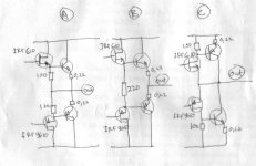
Thinking about what Wenye and Sam9 said, maybe CFP is really a buffer with 100% feedback. This have advantage and disadvantages in audio power amp.
So, CFP is a good candidate for differential and final stage, but not in VAS.
I was inspired by Mr John Curl amp. He uses mosfet as driver and bipolar as output stage. The advantage is this mosfets blocks the final stage from previous stage. I wanted to build class AB amp, so bipolar output stage is the choice here.
A. Is the one Mr John Curl uses. The driver also drives output by resistors.
B. Is the one Doug Self suggested (he use all bipolars). The driver doesn't drive output directly.
C. CFP. I was impressed by the behaviour of CFP. So I think this is also a good candidate.
Which one is the best for output stage?
Which is the most similiar to discrete IGBT?
Attachments
Hi, Mike,
But the question is, why in my experiment preamp (that doesnt use R but transformer's primary) as load, the CFP acts differently than A or B cct? Both A and B doesnt use R, but they have gain. CFP doesnt have it in this experiment preamp.
You are right. We can get voltage gain if we put R in a device which has current gain.The CFP has enormous current gain. Of course you can get only voltage gain with a resistor on the "upper" side. (or currentmirror)
But the question is, why in my experiment preamp (that doesnt use R but transformer's primary) as load, the CFP acts differently than A or B cct? Both A and B doesnt use R, but they have gain. CFP doesnt have it in this experiment preamp.
Dont follow it. My english is bad. Drawings please?I found another way to achieve similar results. I "castrated" a currentmirror.Without this castration bandwidth dropped above 100hz.
(Not a realistic value as there was no load at all)
With 33ohm emitterresistors and a 22k between the 2 collectors
i dropped the gain to that of a cfp with 10ohm Re's. Then
bandwidth is above 10khz, and harmonics drop to -80db.
(2nd harmonic mostly,other at noiselevel)
The gain in this circuit was ~1:100. (sk170 as transistors,bc556b
as currentmirrors)
Thats the important thing.in linearizing.
Hi lumanauw !
For your outputstage, i think 'A' is closest to IGBT. For ClassAB
output i would prefer 'B', it has the advantage that the drivers
operate pure ClassA. With 'A' you have the risk that one of the
drivers closes, but on the other hand it has the advantage of
a local feedback.
A typical CFP-output has the 0.22ohm at the collectorside of the
outputdevices, with the source/emitter connected to the collector
of the output. But you need a large current through the drivers,so
the 100ohm might be too large. I would prefer some 10-20ohm.
that makes ~50mA. Otherwise you might not have enough current
to charge/discharge the inputcapacitance of the base. (would give
bad on/off times, in theory). But Elliott uses 220ohm... Take a look:
http://sound.westhost.com/project3a.htm
I think he loves CFP-output...
At this moment i'm not at home, i can upload a schematic later.
(the currentmirrorthing, but was only a quick check, have to check
if this really works in a complete amp, or changes anything)
I had the experience that cfp-vamp might not work if it's output is
connected to a "fix" voltage. I had problems getting a cfp into
your folded cascode amp. It only worked with an additional resistor.
Just try and add 1k/2k to your testcircuit.
Mike
Re: Which output stage?
I think the B is the best. The C is not really stable for bias. Maybe real CFP with MOS+BJT sholud be better. So move the 0R22 resistors to the collector of the output BJTs, and connect the sources to the collectors as well.
Generally I have no too good results with IRFs in push pull application.
I think the best is to use BJTs at the output stage. I use triple darlingtons, because they provide really lo output impedace without large feedback.
sajti
lumanauw said:Thinking about what Wenye and Sam9 said, maybe CFP is really a buffer with 100% feedback. This have advantage and disadvantages in audio power amp.
So, CFP is a good candidate for differential and final stage, but not in VAS.
I was inspired by Mr John Curl amp. He uses mosfet as driver and bipolar as output stage. The advantage is this mosfets blocks the final stage from previous stage. I wanted to build class AB amp, so bipolar output stage is the choice here.
A. Is the one Mr John Curl uses. The driver also drives output by resistors.
B. Is the one Doug Self suggested (he use all bipolars). The driver doesn't drive output directly.
C. CFP. I was impressed by the behaviour of CFP. So I think this is also a good candidate.
Which one is the best for output stage?
Which is the most similiar to discrete IGBT?
I think the B is the best. The C is not really stable for bias. Maybe real CFP with MOS+BJT sholud be better. So move the 0R22 resistors to the collector of the output BJTs, and connect the sources to the collectors as well.
Generally I have no too good results with IRFs in push pull application.
I think the best is to use BJTs at the output stage. I use triple darlingtons, because they provide really lo output impedace without large feedback.
sajti
MikeB said:Hi lumanauw !
For your outputstage, i think 'A' is closest to IGBT. For ClassAB
output i would prefer 'B', it has the advantage that the drivers
operate pure ClassA. With 'A' you have the risk that one of the
drivers closes, but on the other hand it has the advantage of
a local feedback.
A typical CFP-output has the 0.22ohm at the collectorside of the
outputdevices, with the source/emitter connected to the collector
of the output. But you need a large current through the drivers,so
the 100ohm might be too large. I would prefer some 10-20ohm.
that makes ~50mA. Otherwise you might not have enough current
to charge/discharge the inputcapacitance of the base. (would give
bad on/off times, in theory). But Elliott uses 220ohm... Take a look:
http://sound.westhost.com/project3a.htm
I think he loves CFP-output...
Mike
You have right regarding the low value resistor for CFP output stages. But there is another solution: Add small capacitor -say 10-22nF- between the bases of the output BJTs. This speed up the turn off, without increase the bias on the driver. I tested it, it works
sajti
CFP for current mirror....how?
Hi, Sajti,
Back to CFP. It's properties is unique, I think it is perfectfor making current mirrors. But I dont know how to connect 2 CFP's to make current mirror.
In ordinary current mirror, there are 2 transistors, with small emitor degeneration. Both bases are tied together, and also tied to the collector of one transistor.
1. In ordinary current mirror, what is the purpose of these base junction is tied to one collector? To give current to bases? If it only tied bases only (without one to one collector), the current mirror wont work?
2. I tried to sketch this method with 2 cfp's and it doesnt work. The whole configuration is a mess.
Anyone knows how to tied 2 cfp's to make a working current mirror?
Hi, Sajti,
Do you mean cross C 10-22nF put between base of PNP and base of NPN? I hope my interpretation is right.. But there is another solution: Add small capacitor -say 10-22nF- between the bases of the output BJTs. This speed up the turn off, without increase the bias on the driver. I tested it, it works
Back to CFP. It's properties is unique, I think it is perfectfor making current mirrors. But I dont know how to connect 2 CFP's to make current mirror.
In ordinary current mirror, there are 2 transistors, with small emitor degeneration. Both bases are tied together, and also tied to the collector of one transistor.
1. In ordinary current mirror, what is the purpose of these base junction is tied to one collector? To give current to bases? If it only tied bases only (without one to one collector), the current mirror wont work?
2. I tried to sketch this method with 2 cfp's and it doesnt work. The whole configuration is a mess.
Anyone knows how to tied 2 cfp's to make a working current mirror?
- Status
- This old topic is closed. If you want to reopen this topic, contact a moderator using the "Report Post" button.
- Home
- Amplifiers
- Solid State
- Transistor sounds