Hi
I just finish my buffer amp modular design and build a sample.
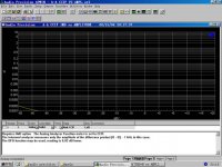
I use audioprecision's system two (2322) to measure it, I got execllent result! In IMD testing I got a near zero(measurement limit of testing equiment)! Other testings results like THD+N, noise floor, lineartly,etc. were show execllent performance!
I think there are no commercial open-loop buffer amp IC or Modular can reach this performance! Even if the well know good buffer amp as BUF-03, OPA-633, BUF-634, etc. are not able to reach such high performance!
Here is a CCIF IMD vs amplitude testing result:
I just finish my buffer amp modular design and build a sample.
I use audioprecision's system two (2322) to measure it, I got execllent result! In IMD testing I got a near zero(measurement limit of testing equiment)! Other testings results like THD+N, noise floor, lineartly,etc. were show execllent performance!
I think there are no commercial open-loop buffer amp IC or Modular can reach this performance! Even if the well know good buffer amp as BUF-03, OPA-633, BUF-634, etc. are not able to reach such high performance!
Here is a CCIF IMD vs amplitude testing result:
Attachments
Thank you ELarson,
It's a open-loop buffer with a non-feedback distortion reduce technology ( a bit like pre-distortion, but different ). I spend around half a year on it's research and design......
Thanks to open-loop(non-feedback) buffering technology it got execllent IMD performance. And also thanks to my non-feedback distortion reduce technology, even if non good matching between transistors, we also got a result in THD+N testing...
Of course, "good matching good performance", still a law...
wenye said:Thank you ELarson,
It's a open-loop buffer with a non-feedback distortion reduce technology ( a bit like pre-distortion, but different ). I spend around half a year on it's research and design......
Thanks to open-loop(non-feedback) buffering technology it got execllent IMD performance. And also thanks to my non-feedback distortion reduce technology, even if non good matching between transistors, we also got a result in THD+N testing...
Of course, "good matching good performance", still a law...
Hi Weyne,
Good to see someone else out there doing open loop buffers
The measurements look great but at what load? I would suggest
re-doing them with a 600ohm load to give the buffer some real
stress and then see what harmonics are being generated.
Further, if you have designed an open loop buffer then it would
appear that you would drive it from an open loop front end. This
means a finite driving impedance and not the low Z OP from AP
test set. So I do all my AP buffer measurements WITH a 20k
resistor between AP and buffer AND into a 600 ohm load from
1kHz up to 20kHz and look at spectrum on FFT. This is a "real
world" stress test.
So far the best I get is about 0.0008% at 2V RMS into 600ohm
load driven by 20k source Z. This is pretty flat to 10kHz and
consists of H2 (most) and H3 (less) only (rest buried). At 5V RMS
-> 600ohms it rises to 0.0015%.
This, of course will say not too much of how it will sound but is
a good optimising tool for a given sonically preferred topology.
Cheers,
Terry
Hi Terry,
I'm happy to see there are someone doing open loop buffers and having success on it.
All of these results were measured under 1K resisitant loading. I can not understand why you suggest me to re-do it by a 600ohm load? As my knowledge, 600ohm as a standard balance I/O impedance in pro-audio system. So, the equivalent loading of each output buffer(hot or cold pin) is 300ohm. Then we can evaluate the same system performance as 600ohm balance load in a singal-end system using 300ohm load.
And you mention about the word "real-world". So, I think the resistant load can not give us a result like "real-world" condition. We also need to considering the load capacitance. Even if 100pF capacitance can make a big difference result. Especially in amplifing system with NFB. Okay, I will re-do these test with capacitance load, thank you for remind me this metter
Correct, I would drive it from an open loop front end still under design. Maybe the impendance is 1K maybe is 10K or more... But, I really interest in what performance difference when driven impendance increase from 20ohm to 20Kohm.... Hum... I'll try it too... Could you share us you testing result difference of this change?
0.0008% at 2Vrms is great, but the result for what? THD+N vs frequency? or something else?
Will do a listenning test after all performance... maybe in this week-end, maybe latter...
wenye said:Hi Terry,
I'm happy to see there are someone doing open loop buffers and having success on it.
All of these results were measured under 1K resisitant loading.
So you are saying that this buffer does 0.0002% SMPTE IMD
at 10V RMS (+20dBV) into a 1k load? That is pretty darn good
for a *true* open loop design.
It would be easy to acheive with even local FB such as a CFP type
design. You have to be a little bit careful with definitions as you
have stated there is distortion cancelling circuitry in the design. I
have designed and also measured a few types of distortion
cancelling circuits in buffers and DAC I-V's but they always
depend on "looking" at the OP's non linearity and correcting for it,
as such I would classify this as feedback, but it's a little bit of an
interpretation issue. Having said the above all the designs
without the extra linearising circuitry tended to sound better
(strange), refer to Nelson Pass's comments WRT Hawksford
power amp OP distortion correction circuitry.
I can not understand why you suggest me to re-do it by a 600ohm load? As my knowledge, 600ohm as a standard balance I/O impedance in pro-audio system. So, the equivalent loading of each output buffer(hot or cold pin) is 300ohm. Then we can evaluate the same system performance as 600ohm balance load in a singal-end system using 300ohm load.
WRT 600ohm load, most of our designs are aimed at pro audio
use and 600 ohm bal or unbal is a generally assumed max load
condition as carried on from the transformer days and plenty
of studios still have some percentage of 600 ohm stuff. If it is
balanced then each leg will swing 1/2 voltage so no need to
go to 300 ohms. It is also a just good all round "hard" load
for the DUT.
And you mention about the word "real-world". So, I think the resistant load can not give us a result like "real-world" condition. We also need to considering the load capacitance. Even if 100pF capacitance can make a big difference result. Especially in amplifing system with NFB. Okay, I will re-do these test with capacitance load, thank you for remind me this metter
Probably a good idea, especially for stability. I recommend
running 10kHz square wave into cap / inductive loads and
check for stability. You may need some value of OP decoupling
resistor, especially if the distortion cancelling circuitry is
interactive with OP. We recently did a job for Sydney Opera
House and the original AE's thought nothing of running line level
audio through up to 300 metres of cabling which ends up as
nF cap loading. There's also plenty of line level isolation
transformers in there aswell all imposing their particular load
characteristics.
Correct, I would drive it from an open loop front end still under design. Maybe the impendance is 1K maybe is 10K or more... But, I really interest in what performance difference when driven impendance increase from 20ohm to 20Kohm.... Hum... I'll try it too... Could you share us you testing result difference of this change?
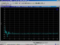
My first designs were not as tolerant to input impedance,
especially as frequency rises so I developed better designs
until they measured almost the same from 100 ohms IP Z to
20k IP Z. This became one of my design criteria. The figures
below are only marginally improved with 100R source Z and that
is probably some noise.
0.0008% at 2Vrms is great, but the result for what? THD+N vs frequency? or something else?
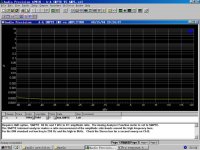
This is THD+N with 20k IP Z (as stated) and from 1kHz to 10kHz.
At 30kHz it is only slightly worse. As stated the harmonic
spectrum is mostly 2nd and some 3rd, I can't see anything
higher.
It's also worth noting that when measuring 20kHz and higher
distortion to allow measuring bandwidth of 10x fundamental
(200kHz) so you will get up to 10th harmonic otherwise AP will
filter these out with it's internal low pass filters. The extra BW will
increase noise a little but it's the only fair way to do it.
Cheers,
Terry
Sharing information
My understanding of this forum is to share information for the benefit of all members. To this end I would like to see circuit diagrams with parts lists of the mentioned circuits so that we could all learn from these designs and enjoy building, testing or perhaps just making a comment on them.
My understanding of this forum is to share information for the benefit of all members. To this end I would like to see circuit diagrams with parts lists of the mentioned circuits so that we could all learn from these designs and enjoy building, testing or perhaps just making a comment on them.
Welcome back alaskanaudio (Johannes). You have been away for a long time. What has happen to your homepage? It has been down for a long time now.
Anyway, sharing is volunteerly. I admit though that it gives us more if you can do more than admire distortion graphs.
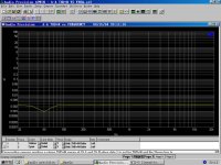
Is it a diamond buffer perhaps?
My diamond buffer has also good performance
Anyway, sharing is volunteerly. I admit though that it gives us more if you can do more than admire distortion graphs.
Is it a diamond buffer perhaps?
My diamond buffer has also good performance
An externally hosted image should be here but it was not working when we last tested it.
Re: Sharing information
I also would add that a schematic diagram would increase the confidence that such a piece of hardware actually exists.
Jan Didden
alaskanaudio said:My understanding of this forum is to share information for the benefit of all members. To this end I would like to see circuit diagrams with parts lists of the mentioned circuits so that we could all learn from these designs and enjoy building, testing or perhaps just making a comment on them.
I also would add that a schematic diagram would increase the confidence that such a piece of hardware actually exists.
Jan Didden
Hi, Terry,
1. I just found a mistake in my testing. The load is 10Kohm not 1Kohm! The color code orange usually looks like red So, I need to do it again with "real 1Kohm" resistant load.
2. Distortion reduce. The implement what I use was a bit like "pre-distortion". There was none op-like and none feedback-like circuit used in this design. I think and I would like to say it's an open-loop buffer design.
3. This buffer was design for cd/pre-amp's signal-end output buffering and active filter. So, the load 10kohm is fair even if I original intention to use 1kohm load to measurement it. I think the testing result still valued. Is it right?
4. I think it's really a challenge for design an amplifier to drive such a complex load as you say the Sydney opera house project. I think nobady will use such a long cable at home. So I will test the modular with less complex load then you did.
5. Really a good suggestion! I will try to test the performance at input impendance for 20ohm to 20kohm.
Thank you
Wenye
1. I just found a mistake in my testing. The load is 10Kohm not 1Kohm! The color code orange usually looks like red
So, I need to do it again with "real 1Kohm" resistant load.2. Distortion reduce. The implement what I use was a bit like "pre-distortion". There was none op-like and none feedback-like circuit used in this design. I think and I would like to say it's an open-loop buffer design.
3. This buffer was design for cd/pre-amp's signal-end output buffering and active filter. So, the load 10kohm is fair even if I original intention to use 1kohm load to measurement it. I think the testing result still valued. Is it right?
4. I think it's really a challenge for design an amplifier to drive such a complex load as you say the Sydney opera house project. I think nobady will use such a long cable at home. So I will test the modular with less complex load then you did.
5. Really a good suggestion! I will try to test the performance at input impendance for 20ohm to 20kohm.
Thank you
Wenye
Tony, alaskanaudio,
I agree with you that sharing a design or an idea is good for diyer. But I will say sorry to you guys I can not share the detail of this design to you at this time. Because it's a coming commercial product of our design team, it's our bread, sorry. I'm happy to share my diy design and commercial product's testing result. sorry.
peranders,
Good work! Your design looks wonderful. My buffer modular is base on "cross coupling" output stage......
janneman,
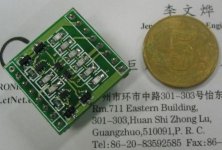
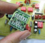
You can find my attach file before for the "looking" of this modular. Then you will know it's really exists.
Rgds,
Wenye
I agree with you that sharing a design or an idea is good for diyer. But I will say sorry to you guys I can not share the detail of this design to you at this time. Because it's a coming commercial product of our design team, it's our bread, sorry. I'm happy to share my diy design and commercial product's testing result. sorry.
peranders,
Good work! Your design looks wonderful. My buffer modular is base on "cross coupling" output stage......
janneman,
You can find my attach file before for the "looking" of this modular. Then you will know it's really exists.
Rgds,
Wenye
wenye said:[snip]janneman,
You can find my attach file before for the "looking" of this modular. Then you will know it's really exists.
Rgds,
Wenye
Ahh yes, that's true. I don't want to insult you either, but after having been fooled a few times too much, one becomes sceptic. We all know that anybody can produce those plots, even without a Device Under Test, heck, even without any AP hardware.
Waiting for the schematic...
Jan Didden
- Status
- This old topic is closed. If you want to reopen this topic, contact a moderator using the "Report Post" button.
- Home
- Amplifiers
- Solid State
- Near ZERO IMD buffer amp