wenye said:peranders,
Good work! Your design looks wonderful. My buffer modular is base on "cross coupling" output stage......
IME,your modular is based on the Daimond Buffer ,same as peranders
") ...cause the "cross coupling" output stage in Chinese expressed Daimond Buffer.
...cause the "cross coupling" output stage in Chinese expressed Daimond Buffer.

Comment on Low Distortion Numbers
Here is a short note on very low distortion figures and a potential hidden problem than can be caused by playing the numbers game.
My concern with any amplifier with multiple stages is with the method of measurement of the published results. Only two points are normally considered in these distortion measurements, the input and the output. No consideration is given to the distortion at intermediate points in the chain from input to output. In a true linear amplifier the measured distortion should be the same at each point in signal path. With the application of any kind of feedback, error correction, pre-distortion or whatever you want to call it have you will have higher distortion levels in the intermediate stages. This intermediate stage distortion can be very high even though the distortion at the output may look truly outstanding. This is likely to be detrimental to the reproduction of the music.
To uncover this hidden and often-overlooked problem is to measure the distortion at various points in the intermediate stages. If distortion-measuring equipment is not available a scope and a good triangle wave can be used as a signal source for testing. If the slopes of the waveform measured in the intermediate stages are not perfectly straight, but straight on the output then we have introduced some kind of error correcting factor. This show intermediate stage distortion and is likely the reason that many amplifiers with minimal or no feedback can sound better that those with extremely low measured distortion figures. If you play the numbers game trying to get the lowest measured distortion figures you may not always be the winner in sound quality.
Care should be taken when measuring distortion in the intermediate stages is it is easy to change circuit parameters or cause oscillations that may prove fatal to the equipment under test. Triangle wave frequency should be set high enough to be able to reach the upper frequency limit of the device under test, but low enough as to not round of the peaks to badly. Feel free to disagree with me about the importance of maintaining equal or near equal distortion levels at all points in a circuit.
Peranders,
Thanks of having noted my absence.
I have been to busy adding on to our house and doing Labview programming in the last two years. My audio web site has had to be ignored while all this work was in progress and only one page is accessible, and that page is no longer valid. Some day I will have time to post some new projects on the site it. Most have found my projects to be too complicated. I have some new designs that I had started working on that are not complete for the same reason mentioned above. The one that is almost complete is a discrete MOSFET OPamp that can drive 50-ohm loads. It was initially designed to drive MOSFET output stages in a new power amplifier. Minor work has to be done on the printed circuit board layout to insure excellent common mode rejection at 100khz plus. At few pf of circuit board capacitance can make a big difference in common mode rejection performance. There is nothing unusual about the overall design since it follows well-known technology with gain and feedback factors set as low as possible. It will make and excellent line driver or headphone amplifier.
I will also be working on a new moving coil phono preamp in the near future. If anyone has an outstanding circuit they wish to share I would welcome receiving it.
Winter is coming and it is time to get back into building electronic toys. I have a lot of circuit board material waiting to be turned into useful things.
Johannes
wenye said:Hi, Terry,
1. I just found a mistake in my testing. The load is 10Kohm not
1Kohm! The color code orange usually looks like red
So, I need to do it again with "real 1Kohm" resistant load.
Well, it will surely measure worse with the 1k load however
the nice thing will be you can see the harmonic spectrum more
easily.
2. Distortion reduce. The implement what I use was a bit
like "pre-distortion". There was none op-like and none feedback-
like circuit used in this design. I think and I would like to say it's
an open-loop buffer design.
OK, sounds interesting and novel, that's good. Another good
reason to try various and herder loads to see how well the
pre distortion works over a variety of conditions. It will also
be interesting to see if the spectrum changes.
3. This buffer was design for cd/pre-amp's signal-end output
buffering and active filter. So, the load 10kohm is fair even if I
original intention to use 1kohm load to measurement it. I think
the testing result still valued. Is it right?
Yes. If you know the conditions it will be used in then no need for
overdesign. Unfortunately we need to cater for worst case
conditions, we never know when someone is going to hang
100's of metres of cable and a few signal splits off a mic pre.
But it's a good challenge and I find high drive capability with
healthy class A always sounds better even into light loads.
4. I think it's really a challenge for design an amplifier to drive
such a complex load as you say the Sydney opera house project.
I think nobady will use such a long cable at home. So I will test
the modular with less complex load then you did.
Ultimately the sound is what's most important, and everyone
has their own design criteria. However as stated make sure you
check stability into various cap loads representative of typical
consumer interconnects. Even some open loop buffers can
oscillate however they usually require less series resistance
to stabilise than a typical opamp.
5. Really a good suggestion! I will try to test the performance at
input impendance for 20ohm to 20kohm.
I think this is important especially WRT it's loading effects on
previous stages. I have found that even tube based followers
had a considerable effect on the previous stages linearity.
Maybe this is some of the reason that so many tube lovers
hate cathode followers, they do have a bad reputation for
sonics although I personally don't share that phobia.
WRT your CD player OP application, it is likely in this case that
the previous stage will have a lower impedance than a typical
pre amp stage so obviously you would use a source R for
measurements that is representative of your particular
application.
Best of luck,
Terry
Just check you test result again.
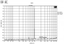
the Sheet show you buffer the THD is 0.0025%(about -92dB),the distortion just so so,same level like good OPAMP.
in you test sheet

show the residure distortion in >5KHz is better but can see more distortion in <2KHz band.meaning in this band the quality must take care( this band more importan for music or voice listen).
in the test we perfer focus in audio quality for listen,so evaluation this module is good or bad no only in one band.
so I hope can have a look all this distortion in 20-2KHz band's distributing.
BTW, can you paste the THD vs RL on 50--100K ohm the perfermance of you idea design?
the Sheet show you buffer the THD is 0.0025%(about -92dB),the distortion just so so,same level like good OPAMP.
in you test sheet
show the residure distortion in >5KHz is better but can see more distortion in <2KHz band.meaning in this band the quality must take care( this band more importan for music or voice listen).
in the test we perfer focus in audio quality for listen,so evaluation this module is good or bad no only in one band.
so I hope can have a look all this distortion in 20-2KHz band's distributing.
BTW, can you paste the THD vs RL on 50--100K ohm the perfermance of you idea design?
PMA said:How about this one? The restriction is not the buffer, but the method
Well, as a speturm analysis result, we don't konw if something like a notch filter been add to the output of DUT. Maybe it can missleading someone. But, as a plot of THD+N vs frequency how do you add a frequcncy changeable filter and make it synchronize change to the measurement generator?
 Even if it can be achieve I don't thing it has good distortion performance. And who will be the monkey? haha! And if you have experience in AP 2X22, you will know there is none filter available for make any of IMD testing result looks beautiful.
 Anyway, you are right a notch filter can make fixed frequency testing result look like good. But sorry, I'm not the guy to make something to spoofing myself.
X.G. said:
IME,your modular is based on the Daimond Buffer ,same as peranders
Okay, sorry for my doesn't understanding the term Daimond Buffer. Thank you for let me know the term.
Rgds,
Wenye
alaskanaudio said:
In a true linear amplifier the measured distortion should be the same at each point in signal path. With the application of any kind of feedback, error correction, pre-distortion or whatever you want to call it have you will have higher distortion levels in the intermediate stages. This intermediate stage distortion can be very high even though the distortion at the output may look truly outstanding. This is likely to be detrimental to the reproduction of the music.
Johannes,
I agree with your point, but not at all.
Ideally, low distortion at anytime slot and anywhere the signal goes through is the best. Unfortunately, for voltage mode amplify technology, it nearly can not be achieved. Usually voltage mode amplifier (call it VMA since here) have very high open-loop gain and depend on deep NFB to achieve stabilization, low distortion and high close-loop bandwidth. When this amplifier works at open-loop status, high distortion will occur at any point of the amp. Thanks for NFB we can see a good looking on periodicity signal. When a high speed signal feed to this kind of amplifier, and signal bandwidth over the open-loop bandwidth of this VMA, then NFB can not correct the distortion immediately, transitory distortion occur. This kind of distortion someone call this thing as "TIM". In VMA, if TIM occur, both signal current and signal voltage of each stage has high distortion. Whether NFB deep or not! The problem is real! Because every natural sound is not periodicity, they consist of very high-speed components. So that almost all of VMA have "TIM" problem. Certainly, limit bandwidth or extend open-loop bandwidth to cover signal BW are compromised solution. Above is theoretically speaking of TIM problem. Have a glance at most solid-state audio amplifier design, VMA and NFB are most common technology which was employ before. And it seems nobody complain about that ¡°they sound bad¡± or ¡°this product employ NFB, so that it sound bad¡± even if NFB employ in hi-end stuffs.
Now, let¡¯s talk about another kind of amplifying technology. It called ¡°current mode amplifying¡±(CMA). In this kind of amplifier design, signal be transfers as current, and convert to voltage at the last node of gain stage. The most important characteristic good for audio or any distortion sense project of CMA is: ¡°even if voltage signal was distorted at I-V conversion stage due to not correct gain setting or any other reasons like TIM, if V-I convert stage work normally signal current still linearity! So now, how to define this stage has distortion or not?
And CMA provide better better open-loop bandwidth then VMA at same of open-loop gain. As we talk above that low open-loop bandwidth will cause TIM directly! And as I said before if open-loop bandwidth over input signal bandwidth, that it will not cause TIM or just a very little TIM we can ignore it. So, now return to your point, you said any NFB or NFB like distortion-canceling technology will cause additional distortion? I don¡¯t think so¡_.. Especially in CMA design¡_¡_
Hi Terry,
Well, it will surely measure worse with the 1k load however
the nice thing will be you can see the harmonic spectrum more
easily.
OK, sounds interesting and novel, that's good. Another good
reason to try various and herder loads to see how well the
pre distortion works over a variety of conditions. It will also
be interesting to see if the spectrum changes.
Agree, so I need to test it again......
Yes. If you know the conditions it will be used in then no need for
overdesign. Unfortunately we need to cater for worst case
conditions, we never know when someone is going to hang
100's of metres of cable and a few signal splits off a mic pre.
But it's a good challenge and I find high drive capability with
healthy class A always sounds better even into light loads.
Ultimately the sound is what's most important, and everyone
has their own design criteria. However as stated make sure you
check stability into various cap loads representative of typical
consumer interconnects. Even some open loop buffers can
oscillate however they usually require less series resistance
to stabilise than a typical opamp.
Congratulate! You found a good way to meet this challenge. That is why I would like to say "real condition" have to drive a high capacitance load. Also need to try...
I think this is important especially WRT it's loading effects on
previous stages. I have found that even tube based followers
had a considerable effect on the previous stages linearity. WRT your CD player OP application, it is likely in this case that
the previous stage will have a lower impedance than a typical
pre amp stage so obviously you would use a source R for
measurements that is representative of your particular
application.
For condition of the test I do before, the input source impedance is around 1.02K...... Happy to try any other source impedance and find what's different.
After 3 days turn it in, it sound better....
Today is not a good luck day. Our AP-2322 was defective by ultra high input ac line voltage. I think the power supply of 2322 was defectived! I measure the incoming ac line voltage after 2322 smoking, actually it as high as 260V!!! It's crazy!!! ..... It seemly have to return it to AP factory....
Could you help me to accomplish other measurements what we (me and you) are concern? If it can be, I will send you 2 or more pcs of this buffer modular for measurement...... Could you?.....
Thanks
Wenye
Well, it will surely measure worse with the 1k load however
the nice thing will be you can see the harmonic spectrum more
easily.
OK, sounds interesting and novel, that's good. Another good
reason to try various and herder loads to see how well the
pre distortion works over a variety of conditions. It will also
be interesting to see if the spectrum changes.
Agree, so I need to test it again......
Yes. If you know the conditions it will be used in then no need for
overdesign. Unfortunately we need to cater for worst case
conditions, we never know when someone is going to hang
100's of metres of cable and a few signal splits off a mic pre.
But it's a good challenge and I find high drive capability with
healthy class A always sounds better even into light loads.
Ultimately the sound is what's most important, and everyone
has their own design criteria. However as stated make sure you
check stability into various cap loads representative of typical
consumer interconnects. Even some open loop buffers can
oscillate however they usually require less series resistance
to stabilise than a typical opamp.
Congratulate! You found a good way to meet this challenge. That is why I would like to say "real condition" have to drive a high capacitance load. Also need to try...
I think this is important especially WRT it's loading effects on
previous stages. I have found that even tube based followers
had a considerable effect on the previous stages linearity. WRT your CD player OP application, it is likely in this case that
the previous stage will have a lower impedance than a typical
pre amp stage so obviously you would use a source R for
measurements that is representative of your particular
application.
For condition of the test I do before, the input source impedance is around 1.02K...... Happy to try any other source impedance and find what's different.
Terry_Demol said:Hi Wenye,
Did you try 1k load on buffer? I'm interested to see spectrum
results.
Cheers,
Terry
After 3 days turn it in, it sound better....
Today is not a good luck day. Our AP-2322 was defective by ultra high input ac line voltage. I think the power supply of 2322 was defectived!
I measure the incoming ac line voltage after 2322 smoking, actually it as high as 260V!!! It's crazy!!! ..... It seemly have to return it to AP factory.... Could you help me to accomplish other measurements what we (me and you) are concern? If it can be, I will send you 2 or more pcs of this buffer modular for measurement...... Could you?.....
Thanks
Wenye
kello said:
the Sheet show you buffer the THD is 0.0025%(about -92dB),the distortion just so so,same level like good OPAMP.
in you test sheet
show the residure distortion in >5KHz is better but can see more distortion in <2KHz band.meaning in this band the quality must take care( this band more importan for music or voice listen).
in the test we perfer focus in audio quality for listen,so evaluation this module is good or bad no only in one band.
so I hope can have a look all this distortion in 20-2KHz band's distributing.
BTW, can you paste the THD vs RL on 50--100K ohm the perfermance of you idea design?
1. THD of open-loop design is not easy to over an op-amp with NFB.
2. The products under 2khz usually cause by measure filter of measurement hardware and software....
3. Just listen to this evaluation board, it sound better after 3days turn in.
Well come to limit number of volunteer to evaluate the modular and give a fair appraisement (not too much contort )...
4. Please find the attach file above THD+N vs frequency.jpg for more detail what you want.
5. THD+N vs load. AP is now not available, could you help me to do the testing?
Rdgs,
Wenye
He he....
Tony!
My HP audio analyzer is working fine.....But I think must take free time using the R&S have a look for calibration and confirm again ....Thanks for you big help...
No problem,Send me you board if you finished ....I'll Check and analysis all performance using the UPD analyzer and soon reply back the result to you.
wenye said:
1. THD of open-loop design is not easy to over an op-amp with NFB.
2. The products under 2khz usually cause by measure filter of measurement hardware and software....
3. Just listen to this evaluation board, it sound better after 3days turn in.
Well come to limit number of volunteer to evaluate the modular and give a fair appraisement (not too much contort )...
4. Please find the attach file above THD+N vs frequency.jpg for more detail what you want.
5. THD+N vs load. AP is now not available, could you help me to do the testing?
Rdgs,
Wenye
I don't think so the <2KHz's distortion is cause by AP2's HW or SW.
still now,I can 't find the THD vs Fr in 20-20KHz@0dB,-20dB test result.
for the THD vs RL,you can appoint the RL load in diffiren choice in 50-100K ohm,normally we using 10K or 100Kohm for normal test.
in test result graph sheet, you can cascade result with difirence RL load.
normally, we perfer the buffer can dirver low impedance lower <1K,e.g 75ohm.if not ,we don't need the buffer.....
--- I can help you for the test,send me the modules,I keep the word about you secret , call me by moblie phone.
- Status
- This old topic is closed. If you want to reopen this topic, contact a moderator using the "Report Post" button.
- Home
- Amplifiers
- Solid State
- Near ZERO IMD buffer amp