
I will do that now.... in one our you will have it Kinser.
Better to use one other small transformer.... and to join the ground pins with your bigger one... this is the best way....because the reduction voltage circuit, will hold 44 volts difference.... will be hot even with small current drain passing trougth... if some damage happens.... your 12 volts circuit will explode!
But, i will do some for you, this way, having both conditions, you will decide the best to your needs....one 15 volts transformer with those positive and negative regulators you already know, or the 56 volts going into one poor devil transistor regulating.
Carlos
Hehe...people like to help...but when good help is done.
Your problem are half way resolved... you already think in LM IC three pin regulators... you already realise that cannot use with 56 Volts, because too big, IC will explode!
This way, our friends, normally stay out of this subject, because they now you are near the "discovering"... and this is great to be done by ourselves!
I will suggest you, when you need fast help... ask a very stupid question.... tell you will put a lamp to reduce voltage, or something alike..... they will run to help you, avoiding you to burn your circuit!
hehe....brazilian trick!!!.....it works!
regards,
Carlos
KInsen, this circuit is dangerous... if you short circuit the output...
Transistor will be burned, because current will be bigger than the fuse in one microsecond!..... this way, can go to 5 amps in short period of time, while waiting fuse melt and blow...it takes some time.... small time....but will delay sometime.... you can exceed transistor capacity and Boooooom!.
This way 56 Volts will enter the low voltage circuit.... hehe, i think this is funny, but i am sure you will dislike!
Now, you will have more people here to help you...because Destroyer can "destroy", your amplifier with his destructive idea!
Use a small transformer....15 plus 15 AC, or less voltage.... and use small bridge rectifier and 2200uF condenser.... and LM IC regulators..... 7812 to positive and 7912 to negative....if burns...no problem to your circuit....do not forget to join the earth point with the amplifier's earth point.... the called "star" ground!
"Star" ground is a pretty name for a Ugly conection.... every earth wire same place.... aaaaagh!... ugly!
But works great!
regards,
Carlos
Attachments
Hi kinser,
There will be some heat to get rid of. Use a simple zener / transistor regulator circuit to get most of the way there and divide the heat dissipation. You can add a dropping resistor before the transistor if needed. Follow this with a capacitor and 7812 / 7912 regulators. You can put a 15V 5W zener to ground from each regulator output for protection if you wish. Don't forget to figure out how much heat you need to get rid of! And don't under estimate the ability of a couple watts to really heat things up.
-Chris
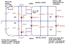
The usual approach employed in consumer equipment to get op-amp rails from power-amp rails when several op-amps have to be powered is to use some cheap series pass transistors [ie: TIP41/42] or darlingtons [ie: TIP122/127] configured as emitter followers [ie: bias resistor from base to 56V, collector to 56V, 15V zener and 100u capacitor from base to ground, 100u capacitor from emitter to ground and you get about 14V with decent regulation at the emitter]
Current capability is limited by the heat sink choice and by the SOA of the devices. For 56V in to 14V out we get about 42*Iout Watts of dissipation. For a dozen of typical dual op-amps at 5mA/device dissipation would be 42*12*.005 = 2.5W, so a heatsink providing 20ºK/W or less would do the job [the case and the main heatsink may be useful too]
This makes more sense than using an extra transformer since regulators and [smaller] heatsinks would be also required
A good way is to use an amplified zener, as other posters have recommended, to drop the voltage to say 20V, then use regular 3 pin regulators to regulate to whatever voltage you need. This spreads dissipation between 2 devices while keeping the lower noise output of the 3 pin regulator. Zener diodes create noise on the supply unless you go to a lot of effort to smooth it out.
I belive Rod has a power supply project showing a zener follower preregulator on his page for precisely this purpose.
I belive Rod has a power supply project showing a zener follower preregulator on his page for precisely this purpose.
The circuit can be devided into two parts. First use emmiter follower with 24w zener diode. use this as input & use 78XX or 79xx circuit. this will be the safest. Heat will also be devided.
It is not good to only rely upon zener diode emmmiter follower circuit. Hope this works.
Mahendra Palesha
It is not good to only rely upon zener diode emmmiter follower circuit. Hope this works.
Mahendra Palesha
Have a look at Rod Elliott's P102. Used one in a sub amp so I could use 7815, 7915 to supply +15v/-15v for a sub processor. Works a treat.
http://sound.westhost.com/project102.htm
http://sound.westhost.com/project102.htm
+/-12V regulator
If you know the voltage required...in this case 12V, all that is needed is how much current you need. It was mentioned to use a Zener diode and a DC emitter follower amp earlier in this thread. This idea will work just fine. I would choose a darlington transistor for this, Vbe is about 1V. This will work just fine and you can use a small cheap zener diode to do this. If you choose a 12V zener, just add two little diodes forward biased in series with the zener to give about 13V on the base of the transistor and the emitter will then output 12V. With the collector tied to the 56V rail through a resistor, use this resistor to set the current limit. 56V-14V=42V so 42V/Rc is the current maximum. Just check the gain (Hfe) of the transistor to choose the resistor to set the current through the zener to make sure the transistor has enough drive. (This is why darlingtons work so good here...Hfe~=1000 or more)
An input filter circuit probably doesn't require much current but even if it does, the circuit topology is the same just use a bigger transistor, maybe heat sink. However, if Rc is chosen correctly more of the heat will be dissapated by the resistor (Rc) not the transistor. I have used this DC emitter follower circuit many times and have had no problems and no noise...if made correctly. This circuit is also cheaper than trying to use a + and - voltage regulator IC, just use PNP for negative side.
You don't need a regulator IC because the transistor is the regulator referenced to the Zener voltage which does not vary when used with low current such as this example. The transistor just amplifies this very steady current.
Good guys, i suppose kinser is young, and we are making a good job
We are sending a lot of working options to him, all them usefull, in the dependence of the material he already has in his junk box.
This kind cooperation is really beautifull, and always made me believe a little bit more in all mankind.
We will survive, keeping our feelings flame burning.
And the peace will follow, as a natural consequence.
Made my day, return here and see all of you.
Carlos
One more thing...
Can't see if anyone have mantioned, but it'll be useful for sure - maximum voltage beetwen input pins of 7812/7912 or 7815/7915 regulators is 35V, regardless of the power dissipation. This means that your regulator will die if input voltage exceeds this limit, no matter how well it's been cooled down. Anyway, try to get datasheet for these regulators and study all sorts of circuits given there. You'll find few answers for yourself, no matter if you'll use them or not. You might need them someday") ...
...
Regards,
Nick
Can't see if anyone have mantioned, but it'll be useful for sure - maximum voltage beetwen input pins of 7812/7912 or 7815/7915 regulators is 35V, regardless of the power dissipation. This means that your regulator will die if input voltage exceeds this limit, no matter how well it's been cooled down. Anyway, try to get datasheet for these regulators and study all sorts of circuits given there. You'll find few answers for yourself, no matter if you'll use them or not. You might need them someday
...Regards,
Nick
- Status
- This old topic is closed. If you want to reopen this topic, contact a moderator using the "Report Post" button.
- Home
- Amplifiers
- Solid State
- from 56vdc +/- to 12vdc +/-