Ok.... so I have a Sony receiver. That's the problem right? STR-DE595. Anyway, I purchased it in order to repair and resell, but the problem seems more complicated than anticipated. It won't turn on at all... no protector mode, etc. The power supply fuse isn't blown, all transistors seem good, transformer is putting out voltages that seem correct (when I manually turn on the AC supply relay). So, I plug it in, and press the power button... nothing. I've tried looking at a bunch of different things, and nothing apparent seems wrong. I'm considering removing all of the relays and testing them individually, but my impression is that relays typically don't go bad. Anyway, any help on what could be the problem or what else I should check would be really helpful. Thanks.
STR-DE595. Anyway, I purchased it in order to repair and resell, but the problem seems more complicated than anticipated. It won't turn on at all... no protector mode, etc. The power supply fuse isn't blown, all transistors seem good, transformer is putting out voltages that seem correct (when I manually turn on the AC supply relay). So, I plug it in, and press the power button... nothing. I've tried looking at a bunch of different things, and nothing apparent seems wrong. I'm considering removing all of the relays and testing them individually, but my impression is that relays typically don't go bad. Anyway, any help on what could be the problem or what else I should check would be really helpful. Thanks.A potential cause of your problem
When I was in the repair business I ran into a number of problems like you describe. I’m not familiar with your particular unit but most of the newer equipment such as this is controlled by microprocessor mounted on the front panel circuit board. This processor may not be getting power or is being held in a reset condition. This will cause the symptoms you describe and the receiver remains off. If your unit has such a processor you may need a circuit diagram to help follow the power and reset paths. You could have a failed processor, but it would be wise to check all of its supply and control voltages before replacing it.
When I was in the repair business I ran into a number of problems like you describe. I’m not familiar with your particular unit but most of the newer equipment such as this is controlled by microprocessor mounted on the front panel circuit board. This processor may not be getting power or is being held in a reset condition. This will cause the symptoms you describe and the receiver remains off. If your unit has such a processor you may need a circuit diagram to help follow the power and reset paths. You could have a failed processor, but it would be wise to check all of its supply and control voltages before replacing it.
Hi rkc7,
It sounds like the AC detect circuit may not be working. Look for a approx. 1 uF capacitor feed by a single diode. These tend to go open and hopefully will be an easy fix.
Like alaskanaudio, I am not familiar with this exact receiver, but the circuits should be common to most, in form. If you have a 'scope, look for a big ripple waveform on a small cap that goes to ground. If you see a half wave rectified waveform, it's open for sure.
-Chris
rkc7 said:Ok.... so I have a Sony receiver. That's the problem right?
Hello rkc7, I have a service manual for that receiver in PDF format, I can upload it to you if needed. It is about 6 MB in size. While you're at it, check the standby transformer, those are known for opening up the primary, which will cause a dead receiver.
If your mailbox can handle a 6MB file, please let me know at rimband@hotmail.com (not my DSL account). I'll E-mail you through my DSL account and upload the manual for you!
Joe
Wow, thanks for all of the advice. Unfortunately, I don't have a scope, just an advanced multimeter that can measure the normal current, voltage, resistance, etc... with diode check, transistor check, and caps up to 200uf. I would be very happy to receive the service manual. You can send the file to skimaniac3@spymac.com, that should have much more than enough space. I'm going to try looking at everything mentioned, and I'll report back. Thanks!
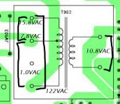
OK... I found a service manual and have done some testing. Capacitors I've tested so far have been good. But I tested the standby transformer and here's what I found:
2 pole side: 11ohms between poles
3 pole side:
between 1,3: 900ohm
between 1,2: open
between 2,3: open
Take a look at the diagram. Pole 1 is the bottom, 2 is middle, 3 is top. Thanks.
2 pole side: 11ohms between poles
3 pole side:
between 1,3: 900ohm
between 1,2: open
between 2,3: open
Take a look at the diagram. Pole 1 is the bottom, 2 is middle, 3 is top. Thanks.
Attachments
Okay,
The standby transformer is not the problem. I'm still betting on the AC detect circuit. Look for a diode feeding a small value cap on the order of 1uF. Measure the AC voltage on the diode, then the DC voltage on the other side. Try measuring the AC voltage across this cap as well. A high AC reading = bad cap.
-Chris
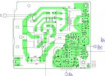
Well, I've been looking for such a feature, but haven't found anything obviously identical to what you say.... here are two pictures of the schematic which may contain the features. The one is the standby board schematic of the pcb layout I posted earlier, the other is from the "digital board" which has the input from the power switch and this section is directly linked to the standby board. I would think what you are talking about would be in one of the two.... so if you could take a look and tell me if you see it.
Standby board
Digital board (power control)
Standby board
Digital board (power control)
Hi rkc7,
Make sure C1617 isn't shorted or leaky, measure the voltage across it. Look at the voltages around IC1605 to see where they differ. Check the emitter of Q1606 (I've seen these open). Finally, check R904 and the voltages on Q901.
Many places to look here, the answer is just waiting.
-Chris
Make sure C1617 isn't shorted or leaky, measure the voltage across it. Look at the voltages around IC1605 to see where they differ. Check the emitter of Q1606 (I've seen these open). Finally, check R904 and the voltages on Q901.
Many places to look here, the answer is just waiting.
-Chris
Banned
Joined 2002
Banned
Joined 2002
I tested all of the specified components without power using capacitance meter, ohmmeter and diode test. I'll try testing them with power if these results don't show anything. Anyway, everything seemed OK except for Q901. Between two poles the foward voltage was about .045V causing my meter to produce continuous tone. This was between the middle point and bottom of Q901 if you look on the original pcb layout I posted. Not quite sure if that means it's bad, but my understanding is that it shouldn't do that. I'll keep looking if that's not it.
You're right... turns out I mixed up the pin position. The short is actually between the top pin and middle, not the bottom. It's the pin marked with "E" on the pcb layout, which I'm guessing stands for emitter. That seems to solve the mystery. But, my next question is would anything else likely be bad as well? I know that with other blown transistors that there's often other things that went wrong as well. I'll check over the board to try to find anything else, but I'm hoping that it was just a bad transistor.
- Status
- This old topic is closed. If you want to reopen this topic, contact a moderator using the "Report Post" button.
- Home
- Amplifiers
- Solid State
- Another broken Sony receiver... won't turn on