So this was on another thread but apparently no one reads that one......or if they do they don't reply to it anymore. I am think of this for my senior design project. I am not looking for solutions just possible issues i may run into.........Just want some input on what every one thinks of this amplifier. The voltage gain setting resistors in the first OPAMP feedback path have not been set yet and I think i will need some small resistance on the sources of the MOSFETS. Other than that I think i am ready to hit the calculator and dig into to this thing deeper and then order parts and start working on a power supply. Fire away folks.
Cory
Cory
Attachments
Hi Cory!
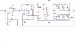
The outputstage is looking strange to me.
You already pointed out some resistors at the source of the
MosFets,... but there seems to be more...
The upper Mosfets would work as voltage followers, while
the lower Mosfets are connected as a voltage gain stage.
If I have a look to the values of R10, R11, R12 & R13 then I assume that you originaly planned to connect also the lower Fets as voltage followers.
But if so, then the high supply voltage rails would not make sense,
as the OP can only drive around +/6V if you really pick the zeners
D1 & D2 with 8V....
This would indicate that the output stage was planned with voltage gain.... Overall, it looks inconsistant to me.
Also combination of positive and negative feedback on the second
OP amp is not a standard configuration, but I did not calculate if these values could work or not...
Last thing:
I do not see any frequency compensation. Oscillation might become
an issue.
Bye
Markus
The mosfets are acting as voltage followers. They are there mereley to supply the current to the load. The voltage is set by the first op amp. The second op amp is a suspended supply. The rails raise and lower with the out put. This allows for a larger swing on the output. The 8V zeners merely maintain the rails at about 8 volts above and below the output (within the limits of the supply).
Hi Cory,
You really should look at that second stage, the pos feedback will surely get you an oscillator instead of an amp.
Also, your choice of opamps seems archaic. The 741 has been abandoned for audio many years ago because of its low performance. The 411 is basically a precision opamp meaning that it is very good for precision DC applications but not so hot for low distortion wideband AC.
The gain setting on the 2nd opamp needs revision I think, as it is it is quite low meaning that the 1st opamp has to provide all the gain, which it cannot do because of its fixed supply. A good number for the gain on the 2nd stage would be 6 or 8; with an output max level of say 50V peak, the 1st stage would need to deliver less than 10V peak in that case.
Jan Didden
Have you actually built this yet?
I get the feeling that the swinging of the second op-amp's power supply with the signal is not going to work well because the feedback is still ground referenced. The feedback needs to be referenced to a floating artificial ground and the conection between stagres would need to be AC coupled. However this will do odd things to the overall DC stability.
Also, the overall voltage gain of this thing will be 2, which is not enough.
Overall, considering that all the monwy is in the case, power supply and power output stage and that the input section costs relatively little, I suggest using a slightly more conventional input/driver stage.
Next to all the previous comments, the common mode input range of your second opamp will be far too small. It should extend to some 40V below the negative supply rail and 40V above the positive supply rail of that opamp. I doubt you will find an opamp that has that wide range. E.g. the negative supply line can be as high as +56V-8V-8V (roughly), so about +40V, while the inputs are still ground referenced. Then better give the output stage some gain and keep the opamps at a fixed (low voltage) supply.
Steven
Steven
...uhps, yes... did not notice the floating supply of the second OP amp.
...and with this the R5 and R6 make sense, you picked R6 much higher than R5 in order to keep the potential of the OP amp input inbetween it's floating rails.... and combined with positive feedback
again a suitable gain is possible...
Wow, funny design!
...probably your heaviest struggle will be the frequency compensation... oscillation...
May be you can put some part of the compensation to the feedback of the first OP amp...
Good Luck
Markus
Hi Steven,
with R6=6.8kOhm and R5=1kOhm the input will move to 48.8V if the
output swings to 56V. At that time the lower Op amp rail will be
around 49V.... OK, this is not proper inside the the common mode input voltage range of the OP amp, but up to 40V output swing it should work.... and as the supply may sag to 45V...50V and the Ugs of the MosFets will add further voltage drop... I think it should work..
In any case there would be the possibility to increase R6.
Bye
Markus
Markus,
Ok, it's not as bad as I thought initially. The resistive divider brings things more into range, but not enough I'm afraid. Still a strange double positive/negative feeback loop around the second opamp. Looks a bit like a Howland current source, if 6k8/10k = 1k/1k8. This is not the case, but not far away.
Steven
my suggestion is:
-use LM317/LM337 stabilizator pair with the 100ohm/1.5k
voltage divider except the zener. It's gonna make about +-18V supply for the opamps and about 38V input to output votage difference(the limit is 40V). Cap also welcome.
-put a second stage of amplification to get up to +-56V mosfets-driving signal.
-think about the compensation
-(optional) put a small capacitor to the ground in the feedback to get huge feedback value for a DC and minimize the output DC
-listen to Chocohoilic's tips (I am a rookie- he is not)
- Status
- This old topic is closed. If you want to reopen this topic, contact a moderator using the "Report Post" button.
- Home
- Amplifiers
- Solid State
- Anything ideas on problems withy this?