Yes, the idea of source follower was to buffer the gain stage so it could drive the large capacitance. But it is probably better with just the smaller FET.
I wonder what can be done to eliminate all the coupling capacitors.
I think I know what you mean about having your imagination run you into the ground. I tend to do it every day at work designing integrated circuits, which is a slow and rather detail oriented process. Which has the upside that I get to "play with electronics" all day at work, downside of making me less inclined to spend any time actually playing with electronics.
The acid test
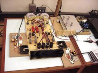
Well I conected the rats nest up and closed the feedback loop and the thing oscillated something awful. I was feeling a bit lazy so I just disconnected the loop and had another listen. Well! I played Enya's Orinoco Flow and I heard things on that track that I had never notice before. It was just so smooth and clear. The vocals were just so easy on the ear. I kept on forgetting I was supposed to be sussing out the amp!
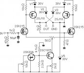
I think the oscillation was from the input capacitance of the output fets in combination with the source and drain resistor of the phase splitter causing rolloff and therefore phase shift. That's a very naughty thing to do inside a feedback loop. So I have fiddled the earlier circuit that has the lower symmetrical output impedance and I will try and drive the output fet gates directly. If there is any oscillation I will add gate resistance bit by bit. I am seriously thinking of going the path of no overall negative feedback, I was so blown away at the results. Here's the cct of what I plan to try next.
Well I conected the rats nest up and closed the feedback loop and the thing oscillated something awful.
I was feeling a bit lazy so I just disconnected the loop and had another listen. Well! I played Enya's Orinoco Flow and I heard things on that track that I had never notice before. It was just so smooth and clear. The vocals were just so easy on the ear. I kept on forgetting I was supposed to be sussing out the amp! I think the oscillation was from the input capacitance of the output fets in combination with the source and drain resistor of the phase splitter causing rolloff and therefore phase shift. That's a very naughty thing to do inside a feedback loop. So I have fiddled the earlier circuit that has the lower symmetrical output impedance and I will try and drive the output fet gates directly. If there is any oscillation I will add gate resistance bit by bit. I am seriously thinking of going the path of no overall negative feedback, I was so blown away at the results. Here's the cct of what I plan to try next.
Attachments
That cross coupled driver cct that I thought looked so good on paper, well it just oscillates! The output from one drain is coupled to the opposite source which acts as an input, then it comes out that side drain and to the other source.... The whole signal goes around and around in a figure 8.
Nothing beats a bit of experimenting on the bench.
GP.
Nothing beats a bit of experimenting on the bench.
GP.
Hi guys, at least our Circlotron is running.
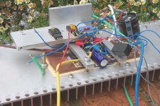
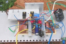
It is a full balanced hybrid circuit made with a single ECC99 double triode tube and a couple of BUZ900 power mosfet. The PSU is a single rail 40V for each MOS and the power output is around 70W...
The final design was demonstrated at aa italian DIY contest near Modena.
In the pic you can see the two double winding toroidal trafo for each channel and the small toroid for the tube PSU, the driver tube stage and the MOS circuit with the heatsink.
The sound is great!
The preamplifier is also an exclusive design: a Supertotem all tube circuit made wit four 12AU7.
Now wa are working around a definitive PCB before sharing all the project on our site.
ciao
Filippo
www.audiofanatic.it
Attachments
Schemi for Passarelli's Circlotron?
Filippo,
Look at more pics of Passarelli's amp at your site: http://www.audiofanatic.it/Amplificatori/ciclotron/ciclotron.html
- is a schematic available for this circuit?
Thanks
Mike
Filippo,
Look at more pics of Passarelli's amp at your site: http://www.audiofanatic.it/Amplificatori/ciclotron/ciclotron.html
- is a schematic available for this circuit?
Thanks
Mike
"is it same as Mr Circlotron's."
"is it same as Mr Circlotron's."
I was interested in the details of the tube driver stage.
Is anyone considering using a battery PS on the output stage of such an amp?
Also, how does the design being discussed here relate to Tenor's solid state amp - if at all?
Mike
"is it same as Mr Circlotron's."
I was interested in the details of the tube driver stage.
Is anyone considering using a battery PS on the output stage of such an amp?
Also, how does the design being discussed here relate to Tenor's solid state amp - if at all?
Mike
Different in detail but exactly the same principle.john-china said:is it same as Mr Circlotron's.
I am looking for a bias servo appropriate for CSPP/Circlotron power buffer.
For Totem pole output stages there exist a topology designed by William T Chater. By post #40 about
http://www.diyaudio.com/forums/soli...tter-audio-non-complements-audio-power-4.html
you will find more informations.
About
Bias control for power amplifiers
is to find the circuit idea therefore.
Is it possible to perform a conversion of this topology suited for a Circlotron ?
Last edited:
Hi everybody. This is how the project is progressing. As you can see I have made the output into a Sziklai pair on the suggestion of AKSA, (thanks heaps, mate
The fets are now tricked into thinking they are P-channel devices and so the whole circuit is upside down. It looks a bit confusing at first, but take my word for it, the things works. To me it sounds just so smooth and clean. Even through that 3C90-cored input tranny!
Next thing to do is figure out some feedback from output to input because the output impedance is 0.47 ohms courtesy of the "source" resistors (that are connected to the drains).
I have not cranked the volume way up yet because of lack of drive voltage avaliable. I gotta make a preamp for it yet. Doesn't that symmetry of the schematic make your mouth water?
GP.
HI
It is a CFP circlotron ?
http://www.diyaudio.com/forums/atta...sing-n-channel-mosfets-circlotron-18-6-02.gif
Who made a solid state circlotron ?
Last edited:
any news ?I am looking for a bias servo appropriate for CSPP/Circlotron power buffer.
For Totem pole output stages there exist a topology designed by William T Chater. By post #40 about
Only N-Channel MOSFETs (NMOS); better Audio from non complements by Audio Power?
you will find more informations.
About
Bias control for power amplifiers
is to find the circuit idea therefore.
Is it possible to perform a conversion of this topology suited for a Circlotron ?
I did a Circlotron using an MC2100 chassis and autoformers. 6KV8 TV tubes; with the frame grid pentodes set up as cathode followers; for a controlled warm up. Autoformer was set up to reverse polarity; allowing me to run the single voltage amp and provide noninverting output. The autoformer took care of speaker interface issues. Now building all-tube version sans the autoformer.
- Status
- This old topic is closed. If you want to reopen this topic, contact a moderator using the "Report Post" button.
- Home
- Amplifiers
- Solid State
- Circlotron amp using N-channel mosfets