Pratt Truck
Hi Graham,
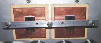
Nice looking truck !.
The copper sub plates are the only proper way to do it IMO.
This will also have good sonic benefit I expect.
If you consider that the audio waveform is assymetric, the power supply imbalance is probably a good thing if the speaker polarity is assigned appropriately.
Continue the good work !.
Regards, Eric.
BTW - Did you get my second transformer email ?.
Hi Graham,
Nice looking truck !.
The copper sub plates are the only proper way to do it IMO.
This will also have good sonic benefit I expect.
If you consider that the audio waveform is assymetric, the power supply imbalance is probably a good thing if the speaker polarity is assigned appropriately.
Continue the good work !.
Regards, Eric.
BTW - Did you get my second transformer email ?.
Thinking of temperature compensated bias here, and particularly the limitations of the "amplified diode" setup that is commonly done by means of a pot across a small temp sensing bipolar. I did mention on another thread that I think that way is wrong because if you adjust the pot to get a different voltage then you also change the gain of the cct so the mV per deg C changes. The quiescent setting might be ok for the temp that you set it at, but as the temp goes up the amp will either "dig in" or "dry out". The exact voltage is important but so is the rate of change of voltage with temp. You need to be able to adjust both, not just the one.
The cct I am thinking about now has both these parameters separately adjustable. On the diagram they are referred to as "offset" and "slope". Here's how it works. The 4 temp sensing diodes have a certain voltage drop at 20 deg C, i.e. cold heatsink. Say 1.2 volts total for the 4 schottky's. Make the TL431 voltage reference equal to 1.2 volts. Actually I just realised it won't go below 2.5 volts so you will have to use a different type of reference. Now as the diodes heat up the LHS of the slope pot remains at 1.2 volts (as in 20 deg C diodes) but the RHS of the pot starts to decrease at 4 times 2.2mV per deg C. If we adjust the pot we can get a temp coefficient anywhere from zero to 8.8mV per deg C.
Turn on the amp. Straight away while it is still cold, with the slope pot fully ACW, dial up the offset pot to whatever it needs to set the cold bias current to the figure you desire. Done. Now watch and wait. As the amp warms the current begins to creep up. You have to set the slope pot for a suitable down-slope of bias vs temp. This is easy. When the temp and therefore the current has crept up a bit, dial the slope pot to bring the current back to where it should be. That's it! Give the amp a good rev up till it gets nice and warm, maybe even get it artificially warm, and then trim the slope pot a little to get the current just right. Now the current should stay fairly constant all the way from cold to hot.
GP.
Attachments
Hi Circlotron,
Pretty neat idea! Having the benefit of hindsight, I was wondering:
If you just put the slope pot across the diode string, you get at the slope pot wiper a variable DC that is temp dependent and can be dialled to any slope from, what was it, 8.8mV/deg C downwards. Then you add the offset for the bias set point. So, it seems you don't need the regulator. What do you think?
Cheers, Jan Didden
Slope pot becomes pot of slop.
If you had the patience to set it correctly it would work ok. The trouble is you set the offset first, then when hot you set slope, but as you change the slope pot it would introduce a whole lot of offset as well. Think of it this way - at 20 deg C the slope pot should have no effect because the diode drop is the same as the reference, but the way you are suggesting even at 20 deg C you have 1.2 volts along the length of the slope pot. Of course if there is a simpler way of doing it I'd love to know!")
If you had the patience to set it correctly it would work ok. The trouble is you set the offset first, then when hot you set slope, but as you change the slope pot it would introduce a whole lot of offset as well. Think of it this way - at 20 deg C the slope pot should have no effect because the diode drop is the same as the reference, but the way you are suggesting even at 20 deg C you have 1.2 volts along the length of the slope pot. Of course if there is a simpler way of doing it I'd love to know!
Jan Didden, I remember your 200W cascode amp in AA a few years back. A brief description to jog peoples' memory. MJE200/210 65Mhz output transistors cascoded with 2N3773. If you want to build a no tears Circlotron with a single pair of 450W 37N50 use the following: A BurrBrown OPA2604 driving MJE200 cascoded with the 37N50. That is it. You're done. Patent #4,229,706 shows all the power supply and bias details. Patent #5,376,899 shows the feedback loop for the Bongiorno amp in figure 7 and how to wire it like the Pass amp in figure 9.
http://164.195.100.11/netacgi/nph-P...&p=1&u=/netahtml/srchnum.htm&r=1&f=G&l=50&s1='4,229,706'.WKU.&OS=PN/4,229,706&RS=PN/4,229,706
http://164.195.100.11/netacgi/nph-P...&p=1&u=/netahtml/srchnum.htm&r=1&f=G&l=50&s1='5,376,899'.WKU.&OS=PN/5,376,899&RS=PN/5,376,899
http://164.195.100.11/netacgi/nph-P...&p=1&u=/netahtml/srchnum.htm&r=1&f=G&l=50&s1='4,229,706'.WKU.&OS=PN/4,229,706&RS=PN/4,229,706
http://164.195.100.11/netacgi/nph-P...&p=1&u=/netahtml/srchnum.htm&r=1&f=G&l=50&s1='5,376,899'.WKU.&OS=PN/5,376,899&RS=PN/5,376,899
Cascode?
We must be thinking of 2 different things when you say "cascode". Could you give me a very rough schematic showing the relative connection of the MJE200 and '37N50. My idead of cascode is that they are both in series and the MJE200 would have to take the full current of the main FET, but the '200 is only a little device. Whats the story?
GP.
No, you're correct. The MJE200 is just a little transistor. Jan used five in parallel in his 200W design, and three 2N3773 for the cascode. The MJE200 is rated at 5A and 15W, the power is soaked up by the 150W cascode device.The Bongiorno Circlotron uses five TO3 in parallel. The point is that by using the Bongorino patent the bias problems are solved. The 37N50 makes a very good choice as the cascode because it needs no drivers and pre-drivers and the one device is rated to handle 450W. The OPA2604 can swing 80V P-P in this circuit with +/- 24V rails. The actual Bongiorno amp used an LF353 with +/- 20V and put out 67V P-P into 4R (about 130W). Should be able to get 200W/4R with the OPA2604. If higher powers are needed a discrete opamp may be built. 400W would be possible with one pair of 37N50 with everything else optimized. Any good BJT with high Beta could be used instead of the MJE200, a single 2SC3281 would be good for 100W/8R.
djk, I suppose then if you went to a cascode cct and really wanted to use hexfets in combination with bipolars then you could use any old low voltage hexfets with a suitable current rating. As far as the Bongiorno bias cct is concerned, when I was looking at it the other night I think it was a class A, which would indeed make it easy to control the bias, but I want to run class AB so above a moderate volume level the average voltage drop across the source resistors starts to rise and that would cause the bias to back right off. I feel to tired and lazy to get up and have another look at the patent at the moment, so would you do it for me please?
Actually, driving a bipolar above a low voltage low Rdson hexfet in cascode was done sometimes in early SMPS's because on switch-off the voltage was across C-B, not C-E, and transistors that have a Vces of 400v typically have a Vcbo of ~700v so that was good. What's more, with the emitter suddenly open circuited the entire switch current is diverted into the base and out the collector (electron current flow) until the C-B junction has all the charges swept out and it turns off. And it's turns off quick smart!
So I wonder then if a hexfet / bipolar *linear* cascode would persuade a relatively slow bipolar to turn off quicker by reducing the storage time? Any current continuing to be conducted because the transistor is a little slow turning off automatically becomes reverse base current and this should be good to help things move quicker. It would be interesting to see how much difference it makes to a slow old slug like a 2N3055.
GP.
Big Breakthrough.
Haven't done too many on-topic posts on this thread for a little while because I have been hard at work getting this cct just right. So many failures and dead ends. So much stuff learned though! And not much point posting stuff that doesn't work! Anyway, the first and most significant thing was a big improvement in output stage linearity when using Hexfets. So many people had commented that bipolars are much more linear than fets, Hexfets in particular, but looking at the graphs of transfer functions of low voltage Hexfets at least didn't look too bad. High voltage switching ones like I am using look pretty awful transfer-function wise. Then it dawned on me... in the IR data book their graphs are log / linear and so the function of drain current vs gate voltage looks like a line with a bit of a bow, but you could live with it. In the IXYS book though, the graph is linear on BOTH axes and the *curve* starts off gradual and gets steeper in approximately a log fashion as the gate voltage increases! D'oh!
To try and iron this out I had been messing around with a Sziklai pair i.e. a pnp and the Hexfet coupled together with a gain of 1. It worked and did improve things a bit but I still wasn't totally happy with it. I tried making the thing a triplet wit a third transistor, and while I could wind the bias up with no input connected, every time I started it up with the driver tranny connected it oscillated and blew the dc fuse. I was starting to get a little tired of this so I lay down for a nap like every good diy'er should when thngs aren't going right.
I was dreaming about the 100R driver collector load resistor that hangs off the fet gate and how it limits the gain of the driver because of it's low value. I though what if I replaced it with a constant current sink that would then give the appearance of many megohms load because as the voltage across it changes the current hardly changes at all. This is sometimes done in voltage amplifying stages, but not usually this close to the output. So I sprung up and ran out to the shed and dug up a pair of LM334Z's and put an 8R2 resistor on each (I wanted 6R8 for 10mA but I had none) and put the current sink ic's in place of the 100R's. Also I replaced the TIP127 PNP darlingtons with TIP30's. They are 100v, 1A, Ft = 3Mhz. I felt rather more comfortable with those.
Anyway, I powered it up and Eureka! The driver transistor gain must have been sky high now because above ~70mA quiescent current it didn't make a scrap of difference to the waveform. Also, looking at the gate waveform with a sinewave input you could really see the driver brute forcing the Hexfet nonlinearity to the weeds An unexpected benefit was that the quiescent current stability was much better; it still rose as things warmed up, just a whole lot slower. The LM334Z's are temperature sensitive and I think they get heat up their leads from the Hexfets. Funny thing though, if you take the drivers off the main heatsink and put them on their own h/s (they only dump ~40mW each), if you warm up the drivers the current increases, but as the Hexfets get hotter the current drops! It may be possible to get them to cancel each other out but I don't think I will bother at this stage.
Temperature compensation. For the bias voltage I ran a 100R 1w resistor from 12v to a forward biased 600v 6A and a Schottky, both TO-220, in series, and with a 200R pot across the pair. I used two different diodes because I wanted a specific voltage across the length of the pot and the position of the pot also influences the mV per deg compensation slope as well as the voltage, as I mentioned previously, and I wanted a particular pot position (slope) as well as a particular output voltage. A bit tricky to get it right but works extremely well when going.
So all in all, the CDA is really starting to honk now. For anyone who turned up their nose at Hexfets because of their nonlinearity, just try them with a constant current sink on the gate drive, the whole thing being a PNP-Hexfet Sziklai pair. Because the gain of the combination in source follower config is 1, the entire internal gain of the pair of devices (perhaps 1000 x 50) is devoted to reducing the nonlinearity and consequent distortion to 1/50,000 of what it would have been. It sounds great! WooHoo! Next thing is to get it into the box.
GP.
Haven't done too many on-topic posts on this thread for a little while because I have been hard at work getting this cct just right. So many failures and dead ends. So much stuff learned though! And not much point posting stuff that doesn't work! Anyway, the first and most significant thing was a big improvement in output stage linearity when using Hexfets. So many people had commented that bipolars are much more linear than fets, Hexfets in particular, but looking at the graphs of transfer functions of low voltage Hexfets at least didn't look too bad. High voltage switching ones like I am using look pretty awful transfer-function wise. Then it dawned on me... in the IR data book their graphs are log / linear and so the function of drain current vs gate voltage looks like a line with a bit of a bow, but you could live with it. In the IXYS book though, the graph is linear on BOTH axes and the *curve* starts off gradual and gets steeper in approximately a log fashion as the gate voltage increases! D'oh!
To try and iron this out I had been messing around with a Sziklai pair i.e. a pnp and the Hexfet coupled together with a gain of 1. It worked and did improve things a bit but I still wasn't totally happy with it. I tried making the thing a triplet wit a third transistor, and while I could wind the bias up with no input connected, every time I started it up with the driver tranny connected it oscillated and blew the dc fuse. I was starting to get a little tired of this so I lay down for a nap like every good diy'er should when thngs aren't going right.
I was dreaming about the 100R driver collector load resistor that hangs off the fet gate and how it limits the gain of the driver because of it's low value. I though what if I replaced it with a constant current sink that would then give the appearance of many megohms load because as the voltage across it changes the current hardly changes at all. This is sometimes done in voltage amplifying stages, but not usually this close to the output. So I sprung up and ran out to the shed and dug up a pair of LM334Z's and put an 8R2 resistor on each (I wanted 6R8 for 10mA but I had none) and put the current sink ic's in place of the 100R's. Also I replaced the TIP127 PNP darlingtons with TIP30's. They are 100v, 1A, Ft = 3Mhz. I felt rather more comfortable with those.
Anyway, I powered it up and Eureka! The driver transistor gain must have been sky high now because above ~70mA quiescent current it didn't make a scrap of difference to the waveform. Also, looking at the gate waveform with a sinewave input you could really see the driver brute forcing the Hexfet nonlinearity to the weeds
An unexpected benefit was that the quiescent current stability was much better; it still rose as things warmed up, just a whole lot slower. The LM334Z's are temperature sensitive and I think they get heat up their leads from the Hexfets. Funny thing though, if you take the drivers off the main heatsink and put them on their own h/s (they only dump ~40mW each), if you warm up the drivers the current increases, but as the Hexfets get hotter the current drops! It may be possible to get them to cancel each other out but I don't think I will bother at this stage.Temperature compensation. For the bias voltage I ran a 100R 1w resistor from 12v to a forward biased 600v 6A and a Schottky, both TO-220, in series, and with a 200R pot across the pair. I used two different diodes because I wanted a specific voltage across the length of the pot and the position of the pot also influences the mV per deg compensation slope as well as the voltage, as I mentioned previously, and I wanted a particular pot position (slope) as well as a particular output voltage. A bit tricky to get it right but works extremely well when going.
So all in all, the CDA is really starting to honk now. For anyone who turned up their nose at Hexfets because of their nonlinearity, just try them with a constant current sink on the gate drive, the whole thing being a PNP-Hexfet Sziklai pair. Because the gain of the combination in source follower config is 1, the entire internal gain of the pair of devices (perhaps 1000 x 50) is devoted to reducing the nonlinearity and consequent distortion to 1/50,000 of what it would have been. It sounds great! WooHoo! Next thing is to get it into the box.
GP.
Hi GP,
You have just made a breakthrough, perhaps more than you realise.
I would like to talk to you about this, can we meet for coffee someplace in Melbourne?
Give me a call on 9457 5591; I'd love to hear from you.
Cheers,
Hugh
www.printedelectronics.com
You have just made a breakthrough, perhaps more than you realise.
I would like to talk to you about this, can we meet for coffee someplace in Melbourne?
Give me a call on 9457 5591; I'd love to hear from you.
Cheers,
Hugh
www.printedelectronics.com
Regarding the 100p cap
... across the pnp transistor, does that not
roll off the gain at a very low frequency so that
the improvement of distortion is also reduced?
I guess it is there for the stability of the circuit,
do you really need that large a cap?
One other way to to lower distortion would be to
cascode the pnp so that the open loop distortion due
to the pnp is reduced, and the n-channel fet would
linearise it further.. no?
And many thanks for drawing our attention to
your breaktrough. Congratulations!
cheers
Hi yves.
The only reason I put the 100pF cap in place was because I was afraid the whole thing would oscillate like crazy when I first powered it up. I just left it there because the thing worked. I'm sure it does roll off the HF, but I haven't yet tried reducing or eliminating it yet. Of course the lower the gain the lower the feedback through the fet.
Cascoding is one thing I have never tried before. I expect you mean to feed the pnp collector into the emitter of another pnp below it, the lower one's base going to a fixed voltage and it's collector going to the current sink and fet gate? Could you post a cct if this isn't what you mean?
If the thing does keep stable then the utterly fearful amount of gain we already have will be further multiplied, and with it the further reduction of Hexfet ugliness. With just two devices, the feedback path is very quick, with three it would be a little slower. However, the TIP30 is a realtively sow device; I only used it because I had one and it has a tab for thermal contact. Maybe a significantly faster transistor or two would make things go well. We are entering an area I don't know much about at all.
GP.
Regarding the cascodes
< Cascoding is one thing I have never tried before. I expect you mean to feed the pnp collector into the emitter of another pnp below it, the lower one's base going to a fixed voltage and it's collector going to the current sink and fet gate? Could you post a cct if this isn't what you mean? >
Yes, this is exactly what I meant.
There have been some posts regarding the sound of
cascodes in the other threads of the forum. I cannot
say anything about that, but if it is purely distortion
we are trying to reduce, then the above is a possibility
provided we can stabilise it , of course.
With the cascode the slightly larger reverse bias
voltage from drain to gate of the fet also reduces
the distortion due to CRSS capacitance nonlinearity.
best regards
Regarding your setup
You can now use a high linearity small signal pnp
as the main signal xtr. One of the BC5xx family should work
since this device dissipates only low power.
Not so sure about the cascode pnp that shields the
small signal though, maybe one of the MJE350 types
are ok, but why not start with the TIP30?
You may want to change the zener to 6.2V 1N821
as they are apparently one of the quietest types.
See
http://ken-gilbert.com/techstuff/triode_connected_pentodesbts.html
for an explanation. I think the low noise has something to
do with the transition from avalanche to zener breakdown mechanism of zener diodes. 6.2V is the magic voltage.
Thanks again for sharing your experiences.
Minor mistake - the drivers dissipate 400mW quiescent i.e. 40v times 10mA (actually a little less) not 40mW like I said.
Cranked up the test rig tonite and put a pair of P-channel hexfets in place of the bipolars. I noticed something that I had overlooked before. At a low signal level I can dial up the bias until crossover distortion just disappears and everything in fine. Turn up the signal level (1 kHz sinewave) further and the crossover distortion comes back until you wind the bias up further to match the higher signal level. It turns out that the moment one of the main hexfets conducts less than 360 degrees therefore moves out of class A, the gate is driven down fast and the hexfet turns of quick instead of tapering off slowly and it leaves a notch in the output waveform. The "source" follower cannot go down further than zero but the local feedback loop gets busy trying to make it do just that.
A quick and dirty fix I will try is running a pair of diodes to the main hexfet gates to bias them on just a little bit, therefore putting a lower limit on the gate voltage so it cannot be completely cut off any part of the cycle. Not real pretty but that is all I can think of at the moment.
GP.
N-fets etc
Circlotron,
This circuit is getting more and more interesting! Are you sure it is the quick turnoff that messes things up? Assuming that I understand you, the turnoff is limited by the current source at the gate. If the feedback is trying to even speed up the turnoff, it must be because it was too slow, and the xover notch would be because of too slow turn off. My suspicion is it would actually be too slow to turn on, because that is limited by the driver.
You could verify this by increasing (or decreasing) the current in the gate current source and see what that does to the effect you saw.
Cheers. Jan Didden
Edit: Your gate resitor is quite large at 1k Ohms, what with the large gate capacitance of these animals. Did you try, say, 100 Ohms here?
- Status
- This old topic is closed. If you want to reopen this topic, contact a moderator using the "Report Post" button.
- Home
- Amplifiers
- Solid State
- Circlotron amp using N-channel mosfets