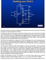
Q3 & Q4 could be darlington drivers, Q2 is bias servo, and should be comparable in beta (Hfe) to be mounted with outputs for thermal stability. Make sure that the transistors you select have a breakdown Vce of at least 100V. I would say you may realistically get 90-100W RMS!
Q1 is an emitter follower, and has no voltage gain...but has a current gain. Rb should be a potentiometer(maybe 47K), and Rt (4.7K) might work, if servo is a darlington type device. As Q2 saturates it turns off the output bias. Turning Q2 off some will allow the outputs to bias class AB and also be linear as far as temp. coefficient.
I would use a current source\current mirror circuit for Ibias as it is more accurate.
Include negative feedback just like any other op-amp circuit, and referenced to ground(0V).
Get a cross reference book to determain the type of devices you may want to use for drivers and outputs. This dosen't look to complex, Good Luck!")
Q1 is an emitter follower, and has no voltage gain...but has a current gain. Rb should be a potentiometer(maybe 47K), and Rt (4.7K) might work, if servo is a darlington type device. As Q2 saturates it turns off the output bias. Turning Q2 off some will allow the outputs to bias class AB and also be linear as far as temp. coefficient.
I would use a current source\current mirror circuit for Ibias as it is more accurate.
Include negative feedback just like any other op-amp circuit, and referenced to ground(0V).
Get a cross reference book to determain the type of devices you may want to use for drivers and outputs. This dosen't look to complex, Good Luck!
- Status
- This old topic is closed. If you want to reopen this topic, contact a moderator using the "Report Post" button.