Just as reference, i do not know how to calculate
But made some thousand amplifiers, this way, life experience and i use one rule.... each 10 RMS watts need 3 by 3 inches side aluminium with 2 milimeters thick... this way 9 squared inches each 10 watts.
My environment temperature normally is 30 degrees Celsius, the centigrade scale. they are working.
Your amplifier is 160 watts power, so, 16 aluminium fins, 3 X 3 inches, if square shape thin, and 16 thins if outside the equipment, without cooler and correct position for convection air movement.
Sorry not to use calculations, since this simple idea works, i started to use simple mathematicas....
9 square inches corresponds to 10 watts
X square inches corresponds to 160 watts.
10X=9X160
Carlos
I'm curious as to how you got 160W per module.
To get 160W average power into an 8-ohm load requires an amplitude of 51V. An amplitude of, say, 63V would give 250W.
If your figures are correct then the psu is +/-65V and the output amplitude is +/-51V. **Assuming** the output transistors connect between the speaker and the 65V power rails,
Worst case, each transistor will dissipate about 50W average and 130W peak.
And this assumes a resistive 8-ohm load.
Do you have the transistor part numbers? If they are rated at 55W/65C they will not be up to the job.
Output devices are 2SK1058/2SJ162. Anthony writes that the amp will deliver:
+-28VDC -> 50W/module
+-50VDC -> 100W/module
+-70VDC -> 200W/module (approxmately, all into 8 Ohms )
If you draw a little grph with this values you get (about, +-30W or something) 160W per modules with +-65VDC supply rails.
The schematic (and some pics) can be found on Anthonys site:
http://www.aussieamplifiers.com/lateral.htm
I guess I need a bigger heatsink...
Konstantin
Ok, I see now that each module has 4 output transistors. This helps.
With +/-65V rails and an 8-ohm resistive load, each module will dissipate 100W average and each transistor will dissipate 25W average and 66W peak. The 2SK1058 is rated at 100W peak power at 25C. So if your heatsink is at 25C and your speaker is 8-ohms resisitve you'll definitely be ok as regards safe operating area of the transistors.
As each module could dissipate 100W average, your shared heatsink must dissipate 200W. At 0.4K/W and air temperature of 25C, the heatsink temperature will reach 105C. At this case temperature, your transistors are only rated at about 40W - thus they will be damaged because they will be dissipating 66W peak and this infringes on the diagonal part of the SOA curve. To allow 66W the case temperature must be kept below about 67C thus requiring a heatsink of 0.2K/W.
 So your heatsink must be at least twice as big/efficient as the one you are contemplating.
Now, from the other thread about device failure it emerges that speakers are not pure resistors and their impedance drops at certain frequencies and so on. It seems to be a sensible rule of thumb to design for half the nominal speaker load as a pure resistance. For an 8-ohm speaker, design for a 4-ohm resistor.
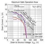
I've attached the load lines per transistor for your amp and power rails. I've shown curves for both 8 and 4 ohm resistive loads. You can see that the SOA is just about ok for 4 ohms, so that's fine too at 25C. A problem occurs when we look at the temperature derating. The transistors can only dissipate 280W peak at 25C and, perhaps 140W peak at 67C. In other words, if you are running your amp continuously at 160W per channel, your heatsink will warm up to 67C and your transistors will then only just work for 4-ohms resistive.
The design needs transistors that are rated at 130W at the required heatsink temperature where the SOA curve starts to be pulse length limited. It appears that the 2SK1058 is just about ok at 67C. It is hard to judge what the SOA curves do as case temperature rises - the only data is for continuous power. So I've assumed that at 67C the power handling is about half that at 25C on all parts of the SOA curve.
I must say, however, that I wouldn't be happy with the reliability of this amp with +/-70V rails and 70C heatsink temperature into real speaker loads.
With +/-65V rails and an 8-ohm resistive load, each module will dissipate 100W average and each transistor will dissipate 25W average and 66W peak. The 2SK1058 is rated at 100W peak power at 25C. So if your heatsink is at 25C and your speaker is 8-ohms resisitve you'll definitely be ok as regards safe operating area of the transistors.
As each module could dissipate 100W average, your shared heatsink must dissipate 200W. At 0.4K/W and air temperature of 25C, the heatsink temperature will reach 105C. At this case temperature, your transistors are only rated at about 40W - thus they will be damaged because they will be dissipating 66W peak and this infringes on the diagonal part of the SOA curve. To allow 66W the case temperature must be kept below about 67C thus requiring a heatsink of 0.2K/W.
So your heatsink must be at least twice as big/efficient as the one you are contemplating.Now, from the other thread about device failure it emerges that speakers are not pure resistors and their impedance drops at certain frequencies and so on. It seems to be a sensible rule of thumb to design for half the nominal speaker load as a pure resistance. For an 8-ohm speaker, design for a 4-ohm resistor.
I've attached the load lines per transistor for your amp and power rails. I've shown curves for both 8 and 4 ohm resistive loads. You can see that the SOA is just about ok for 4 ohms, so that's fine too at 25C. A problem occurs when we look at the temperature derating. The transistors can only dissipate 280W peak at 25C and, perhaps 140W peak at 67C. In other words, if you are running your amp continuously at 160W per channel, your heatsink will warm up to 67C and your transistors will then only just work for 4-ohms resistive.
The design needs transistors that are rated at 130W at the required heatsink temperature where the SOA curve starts to be pulse length limited. It appears that the 2SK1058 is just about ok at 67C. It is hard to judge what the SOA curves do as case temperature rises - the only data is for continuous power. So I've assumed that at 67C the power handling is about half that at 25C on all parts of the SOA curve.
I must say, however, that I wouldn't be happy with the reliability of this amp with +/-70V rails and 70C heatsink temperature into real speaker loads.
Attachments
This is quite a complex thing to work out. On reflection for a moment, it all depends how you interpret the temperature derrating of the 2SK1058.
Another way to look at is it to identify the maximum channel power dissipation of the device, at time periods likely with a music signal. From the SOA curves I look at the point where the curve starts to slope downwards. Here the power is between 210W and 280W depending upon duration. Let's use 280W.
The device can dissipate 280W at 25C. Now to derrate this is uncertain. One way is to look at the continuous power derrating curve and use that. So at 67C the continuous power is reduced by about 40%. If we apply that to the peak we get 280*0.6 = 170W. This is ample for 66W peak dissipation.
At 105C (your 0.4K/W heatsink) the continuous power is derated by about 65%. Peak power may now be only 100W. This is fine for 66W peak but not enough for 4-ohms which needs 130W - a real possibility with a speaker.
To be safe for a 4-ohm resistive load you need 130W peak which is about 54% derating. This implies the heatsink needs to keep the case teperature below 92C.
By this reckoning, you need a heatsink dissipation of better than 0.3K/W at 25C free air temperature, not 0.2K/W as I stated earlier. I think 0.3K/W will be fine if your room is at normal temperatures.
- Status
- This old topic is closed. If you want to reopen this topic, contact a moderator using the "Report Post" button.
- Home
- Amplifiers
- Solid State
- Another heatsink question!