Hello all.
I'm trying to repair an Hill audio DX1500 Power amplifier and I need to find replacements for the originally used H001A B1 NPN Power transistors. I suspect that these transistors are (H001A B1) are ifact some kind of standard bipolar transistor vitch has gone trough a screening / matching process, but I'm not shure.
Anyon that has any info on this ?
Regards
Peter Flodin
Maybe a MJ15003...
OK, Ill try this istead, witch transistor could replace those on the drawing attached ? Rail voltage is +- 80V and rated power is 300w RMS @ 8ohm , 500w RMS @ 4ohm and 750w @ 2ohm.
There seems imposible to obtain the original transistor (H001A B1) and the manufacturer of the amplifier (Hill) doesn't exist anymore.
Could a MJ15003 do it or....
/Peter
Attachments


First, let me ask a couple of questions: Is the transistor in a TO-3 package?
How long ago was the amp first made, 1 year, 10years, more than 10 years? How many parts are in parallel, if any, at the output?
You have MANY choices available, BUT we want to make the replacement device compatable with the original part.
For example, the MJ15003 is a SLOW part, but rugged (for 25 years ago). There are faster parts with the same ratings today, but they are usually in a different package. If the output devices are in parallel, you might have to replace the whole side of parallel devices.

OK, I'll take it from the top.
The amp is a professional power amplifier of the brand Renkus-Heinz but was manufactured by the brittish company Hill Audio Ltd sometime in the late 80s (or early 90s maybe). Each channel is built on eight NPN bipolar transistors (TO3 case), four and four devices in pararell with a with a 0,33 ohm resistor on the emitters.
The rail voltage is +-80V (transformer is 2x65V)
10 out of the 16 transistors seems to be broken (shorted C - E ), so the plan is to replace all the transistors with new ones. I allso found that one of the emitter resistors was broken (infinite resistance), but I don't know if that hapend when the amp broked down.
When this happend the amp was running in bridge mode with a load of 4ohm (two 18" subwoofers, 8ohm each).
It seems to be a litte odd to use only NPN devices, but in the manual the manufacturer says "Using a unique transformer coupled driver stage, the DX1500 features identical ultra-linear NPN output devices connected in a Super A sliding bias configuration exhibiting a much more linear response than conventional amplifiers using NPN and PNP devices." ?????
I have tried to post a clip from the schematics, but it seems to have been lost in transit....
/Peter
Attachments

The original part was probably a house numbered MJ15024, rated at 160W SOA at 80V. The new MJ21196 is 240W SOA at 80V and is the same cost.
http://www.onsemi.com/pub/Collateral/MJ21195-D.PDF
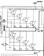
A schematic for the "Hill Heat Generator"
http://www.diyaudio.com/forums/attachment.php?postid=246697
The MJ15003 is only 120W SOA at 80V, but will not take more than ±70V unless hand selected.
http://www.onsemi.com/pub/Collateral/MJ21195-D.PDF
A schematic for the "Hill Heat Generator"
http://www.diyaudio.com/forums/attachment.php?postid=246697
The MJ15003 is only 120W SOA at 80V, but will not take more than ±70V unless hand selected.
Tanks for all help folks.
I probably have to go for the MJ15024 as a replacement since the MJ21195 seems to be a little difficult to obtain here in sweden.
Anyone have an idea what could have caused this chain reaction (10 out of 16 transistors blown..) ? Is running in bridge mode more stressful for the amplifier? As I mentioned earlier, one emitter resistor was broken (infinite resistance), and it's transistor was one of the few survivers so it looks as the resistor broke before the big burn-out, could this have caused it ?
/Peter
pflodin said:Tanks for all help folks.
I probably have to go for the MJ15024 as a replacement since the MJ21195 seems to be a little difficult to obtain here in sweden.
Anyone have an idea what could have caused this chain reaction (10 out of 16 transistors blown..) ? Is running in bridge mode more stressful for the amplifier? As I mentioned earlier, one emitter resistor was broken (infinite resistance), and it's transistor was one of the few survivers so it looks as the resistor broke before the big burn-out, could this have caused it ?
/Peter
Even Avnet in the U.S. is showing an 11 week leadtime on the device -- and you'll have to order 100 pieces.
Both Digi-Key and Future-Active have plenty of stock on the MJ21194
http://www.digikey.com/
http://www.future-active.com/Comergent/en/US/adirect/future?cmd=OnlineOrderingPageDisplay
Be sure and get the 21194 NPN, the 21193/95 are PNP
http://www.digikey.com/
http://www.future-active.com/Comergent/en/US/adirect/future?cmd=OnlineOrderingPageDisplay
Be sure and get the 21194 NPN, the 21193/95 are PNP
djk said:Both Digi-Key and Future-Active have plenty of stock on the MJ21194
http://www.digikey.com/
http://www.future-active.com/Comergent/en/US/adirect/future?cmd=OnlineOrderingPageDisplay
Be sure and get the 21194 NPN, the 21193/95 are PNP
the question of availability was raised with regard to the '95. Besides, the MJL21193/4 are TO-264 cases, not TO-3.
jackinnj said:Besides, the MJL21193/4 are TO-264 cases, not TO-3
Hi,
It is usually no problem at all to mount a TO-264 package at the place where a TO-3 is intended. Base and Emitter leads are at the same place. They fit neatly as well.
Cheers
")
pflodin said:I dont understand this, I try to attach a file several times, but they never show in the message......
I'll try again..
/Peter
Your file is viewable!
. That I guess from your schematic is that your amplifier appear to be a P.A. amplifier. Hence don't worry for speed, high sound quality or other subtleties: in this case they don't count.Djk has suggested good replacements for your output devices; you have just to select a bunch from a lot with the same producer, the same code of production and, roughly, the same Hfe. After you have got the devices you have to mount a little modification to improve safe working of the amplifier: add in serie to each base a resistor between 3 to 5 Ohm of a couple of watt (following the rule: high R with high HFE).
+/- 80 Volts of supply lead the amplifier in the range of 20-25 Amperes maximum when loaded with a 4 Ohm speaker system, that's are not a rambling in the park. 4 transistor for each side are just the minimium for handling currents and powers of these entities (namely 400 watt of dissipation for each side at maximum power output with random - no sinusoidal - audio signal).
Be careful in remounting transistors on heathsinks: the margin for allowing overheating of the output stage appear very tight and may be not really dimensioned for a real continous service on field. If possibile, i suggest a reduction of supply rail from the actual +/-80 Volt to a more safe +/-65 Volt.
It this cannot be done using a new main transformer, may be obtained with "shrinking" of power supply capacitors (i.e using an enhanced ripple as a "drop resistor" for tailoring the supply at maximum power output). A good value may be 10.000+10.000 uF for each channel. Don't go over 15.000+15.000 uF (If the actual filter capacitor are lesser than my minima, LEAVE ALL AS IS! Don't enhance power supply filtering.
Ciao
Piercarlo
pflodin said:Anyone have an idea what could have caused this chain reaction (10 out of 16 transistors blown..) ? Is running in bridge mode more stressful for the amplifier? As I mentioned earlier, one emitter resistor was broken (infinite resistance), and it's transistor was one of the few survivers so it looks as the resistor broke before the big burn-out, could this have caused it ?
*Heavy* thermal breakdown with the "assistance" of second breakdown. That amplifier *cannot* be bridged, it yet at it's power limit as a single ended amplifier If you bridge two of them, you stress the output stage to work out over 40 ampere of current output... Not too healthy if the circuit is not expressily designed to handle it.
Ciao
Piercarlo
pflodin said:It seems to be a litte odd to use only NPN devices, but in the manual the manufacturer says "Using a unique transformer coupled driver stage, the DX1500 features identical ultra-linear NPN output devices connected in a Super A sliding bias configuration exhibiting a much more linear response than conventional amplifiers using NPN and PNP devices." ?????
G'day.
This is just marketing guff unfortunately. That output stage topology may not be common today, but it is in no way unique.
I have technical literature dating back to the late 50's describing it. When people first started making audio power amplifiers for consumer applications (transistor radios, televisions) transformer coupled Class AB push-pull output stages with centre tapped primary output transformers were popular.
This was a rather icky practice borrowed from valve techniques.
The output transformer was rather expensive though, and designers soon started devising circuits to eliminate it. Quasi complementary output stages were mandatory because complementary NPN/PNP pairs simply weren't available.
That output stage topology in you amplifier is in fact one of the very first output-transformer-less BJT quasi complementary designs - and a primitive implementation at that! Most designs of the late 50’s and throughout the 60’s incorporated thermistors with the output stage biasing resistors in an attempt at temperature stabilisation.
This topology was eventually superseded by designs that also eliminated the driver transformer; and they were later superseded by complementary designs when complementary NPN/PNP power transistors became available.
Cheers,
Glen
- Status
- This old topic is closed. If you want to reopen this topic, contact a moderator using the "Report Post" button.
- Home
- Amplifiers
- Solid State
- Hard to find transistor...