I did it, but i am starting to learn those calculations, i feel no secure, can you help me.
First intention is to use hard this thopology, because sounds very nice to my ears, have similarities with AKSA, but not too much, and there are some parts that are not in this schematic.
The second intention is to learn and after multiply this knowledge to friends in this forum....only DC calculations i want, AC is too difficult to mine Mathematics.
I do not know how to calculate first base resistance.
Please, you that have the good will to expend some time, use 25 volts plus and minus, and 25mA each rail.
I will put numbers in resistances in a matter of minutes.
thank you in advance, this circuit is wonderfull.... AKSA cousin!
regards,
Carlos
Attachments
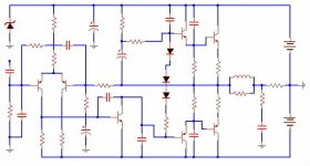
Yes, i already simulate it in Multisim 2001
And the results were very good....but i found some strange values related to gains that confused me a lot.
I do not assemble it yet, but i intended to do and offer those basic DC calculations to our forum friends.... the ones you use ohms law and simple calculations...only DC calculations, using values normally founded in schematics to condensers, and nothing more strange than that.
Please, some friend, give me a help, this way, will help all friends.... if you wanted to explain DC calculations, will do this service in advance to our friends, because my intention is inform them.... not needed that the "informer" was my person...if you wanted, please, enter..... make this place your house....our home...our forum..... if have not time, just inform values, and you are making a explendid job to our friends too.
I decided to to, but i am not prepared to do this.... but i will researching to make those people calculate, at least, this thopology, the best sounding circuit, in my idea.
Of course not the best circuit.... i think AKSA is the best in this Thopology, my idea is that Dean's circuit only loose for old JLH....but has the advantage of more power and less consumption.
My friends are bothering me related AKSA secrets.... i will not give those informs because i cannot.
My circuit is done, when you informed, if ashamed, i will send you mine, simulator tested, direct mailing to you all that help me....but a secret.... sccchhhhh!, do not tell anybody my damn values, top secret crazy values hahahaha!
I am tired to copy, now i will want to do it entirelly.
Here's components numbers...if in doubt related something, take your own decision and inform me please. (alike change Zenner, or include CCS.... at your will)
Mankind schematics, that's the idea, not mine or yours...public dominium.
regards,
Carlos
Attachments
hohohohô now i am happy again..you the first thann
Yes, thank you very much..... that's my chance!!!
Can you hear some noise alike a " Vacuum cleaner"? because i just already switch it "on" to suck your knowledge?
Good chance to me. thannks thann!
1) Why people put those called stop resistors?
2) What they really stop?
3) How can i calculate them?
4) Normally i saw people using 100 ohms to drivers and 10 ohms to output....are they just repeatng others do, or thid value is fixed?
5) Can i see differences in wave shappe in wave form monitor?
6) What happened when you listen the amplifier with, and without those "called" stop resistor.
hohohohohô, is Santa Claus Smile, for Christmas time....what the meaning in Vietnam,,,,is a personnal name alike John?....have translation?...some english version?, some meaning alike "pine tree"?
Thank you very much....you are the one....i was feeling alike an abandoned dog!
I was reading your threads and replies....i like you!
regards
Carlos
I expect hohohô have good meaning!
When i was in Japan, 1981, i was in a restaurant, and sitted together very important people from Sony, all them big staff, the highest one third man in Sony.
But, as i asked them, family gonne together, this is not common there, but i was negociating 3 million dollares package, this way family alowed as an exception.
Womans smile and laugh a lot looking at me, Japanese, very educated those men, a little surprised and talk fast one each other, woman laughing more and more.... and a always use my "indication finger" passing it from down to up position in my beard, to check if well shaved, is a nervous way i have when together people so important, always do that...... do you know the meaning of this, they told me when i was in Narita Airport returning home.
I was so ashamed!.... this means, invitation to go to woman to bed.... you know?....not to sleep!!!
My face turns read, and i return full of shame.
Also the OK" USA signal, if you turn it 180 degrees, point ground, is a bad thing to....bad use to the piece you use to sit on the chairs...The same position as Americans say OK!, means to us:
-Why don't you find a good use to this piece!.... insult here!!! cannot explain more deep.... as deep is the.....
Long finger up is the same here, we do not like Prostatic doctors too!
regards, hehehehê (ashamed smile)
ARE YOU SEEING PEOPLE, THE FIRST TO HELP US ALL, ASIA!!!!, WHERE'S AMERICA?...WHERE'S EUROPE?
Carlos
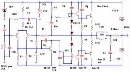
There seems to be a couple of errors on the schematic. The zener on the left should be connected to the junction of the two resistors next to it, not the supply rail. And the connections are wrong on the right diff pair transistor -- it's one line has been cut short and connected in the wrong place -- feedback and VAS is wrong.
Stop resistors work in two ways:
1. Form a low-pass filter with the input capacitance of the device, thus cutting away dangerous high frequencies.
2. Swamping track inductance so that an LC circuit (unstable) is not formed with the track and the device.
Stop resistors work in two ways:
1. Form a low-pass filter with the input capacitance of the device, thus cutting away dangerous high frequencies.
2. Swamping track inductance so that an LC circuit (unstable) is not formed with the track and the device.
do you know the meaning of this, they told me when i was in Narita Airport returning home.
You should have just said "I know", smiled, and got on the plane.
")
OK! Richie Oh! Boy, that's fine to me
And thanks the attention Richie.
My dear Canadian friend.... they are, Japanese people, very honored, those things have other values for them.... a damn insult invite their wifes to bed....i know you are joking... of course
Regards,
Carlos
And thanks the attention Richie.
My dear Canadian friend.... they are, Japanese people, very honored, those things have other values for them.... a damn insult invite their wifes to bed....i know you are joking... of course
Regards,
Carlos
HA ha....yeah I might be 
I wouldn't have felt all that ashamed over it anyway, they should have had enough professionalism about them to not laugh about it, or told you what it meant, so you could laugh along with them, as you can not expect someone to know your culture's oddities.
Placed in that situation however, I likely would have done exactly as you did.
Hi Carlos!
In general I think this schematic is fine.
Also I think the 47uF bootstrapping of the VAS is
OK, even if there are several people who would not like
such bootstrapping. IMHO such bootstrapping is fine as long as the
bootstrapping cap combines a large value and good high frequency properties (may be paralleling 100uF electrolytic and 1uF MKP would allow further improvement).
Why did you choose a 4V7 zener and 3.9k?
I would prefer a 12V zener and 2.7k to the rail, this would allow a higher values for R2 and VR1, which would improve the common mode rejection of the differential stage.
My normal rule of thumb is to go for biasing somwewhere between 0.5mA to 2mA for each tail of the differential amp.
So let's pick 1mA. So with a 12V zener, R2 and VR1 would need to sum up to 5.65 kOhms = (12V-0.7V)/2mA. Why do need VR1? I would use R2 only.. So my proposal is R2=5kOhms and VR1=zero. If you stick to your 4V7 zener, then my proposal would be R2= around 2kOhms, VR = zero.
For R3 I would pick 820 Ohms or 680 Ohms. The voltage drop accross R3 will be around 600mV...680mV. So about 1mA will match and some micro Amps can be delivered to the base of BD139.
R4 I would set to zero.
Do you really want use that much of 10pf caps all around the
output stage?
As long as you are not really sure that you need them, I would propose to remove them for first approach and try to set the dominant pole with the cap between base and collector in your VAS (BD139). For first steps I would start at 100pF first and check in small steps if you can decrease to your desired 22pF....
Furtheron you could think about a small cap across R5.
For the biasing of the VAS I think that around 10mA are OK.
So R6 would be 2.2k or 2.7k , but use 1W types (or parallel three or four small ones, i.e 4x10k ohms in parallel).
R7 should be much less (my guess: 47 Ohms ... 330 Ohms).
Bye
Markus
They are very interesting people... i respect them
Also USA, our main power country on earth last 60 years and the power now a days had the respect and always respect them.
U.S. sent an atomic bomb there, because no enough will to put their feet there, i am sure, those people were prepared to defend land with their own life.
American President was clever, related save american lifes, but maybe with damn problems with his relation with God now!... i do not have sure, but i think was Roosevelt, afraid of lost of thousand lifes, their boys were in big trouble to put feet there, this way decided to send a bomb to make them surrender..... if not a bomb...... hummmmmm, do not know result.
I think was not needed to destroy those towns, Nagazaki and Hiroshima.... better if evaporate one empty Island, to show power
I could perceive, they never go backwards, Japanese knows advance....only forward, very clever and interesting people and culture...i like them very much.
But the Cowboy is boering me too much!!!
regards,
Carlos
ur amp
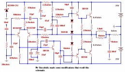
Hi Destroyer ,What are you trying to build? I think the remarks of Chocoholic were very precise ,the only thing i can add to them is that the circuit isn't drown the best way. In order to understand better how it works you could put the VR2 ,R7 and R6 in a line to be seen that it is the load for the VAS -BD139. And finally what about the Zobel network ,doesnt it has to be connected before the RL output network ,not after? Regards!
Hi Destroyer ,What are you trying to build? I think the remarks of Chocoholic were very precise ,the only thing i can add to them is that the circuit isn't drown the best way. In order to understand better how it works you could put the VR2 ,R7 and R6 in a line to be seen that it is the load for the VAS -BD139. And finally what about the Zobel network ,doesnt it has to be connected before the RL output network ,not after? Regards!
Hello Chocoholic and hello hope
And all people that passes here to read, thanks.
Chocoholic, i think we have write messages at the same time, this way i was answering other guy and did not see your message till now, Many thanks, very good help, increase the differential current, and goes reducing the 100 pf capacitor in the Voltage amplifiers transistor....thanks Chocoholic.
I do not know how to calculate the first bias resistor, from the first transistor to ground, i think this one is 10 or 20 times base current, could not understand till now, of course doubts with the feedback one, that goes to second transistor base, the one to reduce gain.
Thanks rope, all i want is understand better, to have some friends inputs, and to develop this one.
At same time i want to learn more, understand more, because i want to teach young boys how to do amplifiers with simple calculations.... to put them to work, not perfectly, but to start a working amplifier by themselves.
As i said, i already have the circuit working in simulation, this is a good step ahead, and i will do Chocoholic changes, this will be next step..... an will keep it rolling for some time.
Thanks you all, The filter, normally is used in parallel with speakers, i prefer to split in two halves, one before and other after the output coil.
If i did not forget, usually i do this way.
regards,
Carlos
Hi Carlos!
You are unsure about the resistor on the very left, at the input
of the amp, correct?
And feedback resistor R5?
Resistor on the very left. It will carry the DC bias current from the basis of the left BC557. If BC557 runs at 1mA collector current we can assume some micro amps in the basis (depending on the current gain of the BC 557, A-type, B-type, C-type? ). This will cause some millivolts voltage drop across this resistor.
Let's have a look to the BC557 on the right. The base current of this one is delivered through the feedback resistor only (1k to ground is DC blocked by 33uF. By the way: 1k+33uF are in fact reasonable and quite universal values for this path, also you picked the correct polarity for the 33uF).
For smallest DC offset, the feedback resistor and the resistor on the very left should have the same value (If both BC557 run at the same collector current and have identical current gain==>same base currents==>same voltage drops at the left resistor and feedback resistor ==> same voltage at both inputs of the differential amp when the output is at zero). Normal range of these resistors would be between 10k and 100k.
Which voltage gain do you want from this amp?
Voltage gain will be approx.: Gain = (Rfeedback/1k) + 1
If you pick 33k...47k for feedback, then normal line signal levels from CD players etc. should work to drive this amp to full power.
By the way: I think this basic traditional circuit is a good choice to teach your young friends.
Bye
Markus
Very good Chocoholic, zier gut!, thank you!
I am happy with your cooperation, and friendship too.
I made the mods, you suggest, i like the result too.
But i will need the informs, how to calculate first resistor.... i will check after, maybe you already put this response.
Your modifications resulted in a better balanced amplifier, but, i was afraid, because some VBE voltages goes to high levels related the first i calculate (try to).
Mine, voltages around 600 milivolts....yours, voltages goes to 620 and 630 milivolts....what this means?..... are we now. more close to saturation?
I Read recently Douglas Self, and he told to put same current in differential transistors, and same resistance values, off course same base current and voltage..... and he explain that...unfortunattelly i could not understand a half the meaning of his words.
Simulation differences:
Your modifications made better square wave up to 60 KHz
Your modifications made worst square wave down 100 hertz
Can you understand those changes...... i forgot the 0.068uf condenser in the output, before was 47 picofarads....but this will turn worst 60 Khz response..... and the all thing became better.
If you can understand, or, want to change more..... our house, our schematic.... go ahead, i will change and show in this thread.
I will put the schematics i made also.
The first one, your corrections added Chocoholic, with my deep thanks!
regards you, and all friends that came to read.
Carlos
Attachments
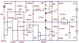
I perceived you already answered input resistor, thanks Chocoholic.
This one, was the amplifier i made calculations....learning how to make, a little confused already, but i will be better in some days.
Thanks, i put the first resistor checking VBEs..... but could not calculate, alike the others.
regards,
Carlos
This one, was the amplifier i made calculations....learning how to make, a little confused already, but i will be better in some days.
Thanks, i put the first resistor checking VBEs..... but could not calculate, alike the others.
regards,
Carlos
Attachments
Please, if you feel capable, do it, teach them
I feel insecure.... if you want, please, go ahead.... all i want is that the boys learned that.
Do not matter if i do or my friend Chocoholic does, for me a honor have you together (really).
I understood 100 percent your informs related base resistor, and the values ratio i choice to put 820 milivolts in the input before the clipping.
Till Tomorrow.
Really, if you feel good to teach calculations, go ahead, i will learn too..... i am already learning.... that's reality.
regards,
Carlos
- Status
- This old topic is closed. If you want to reopen this topic, contact a moderator using the "Report Post" button.
- Home
- Amplifiers
- Solid State
- Can you please calculate this circuit