I've never really looked at using MOSFETs in an amplifier arrangement before, only simple switching applications, so please excuse my ignorance.
For reference, I am looking to use 60Vds to control a maximum current of 50mA.
I was just using Fairchilds FET simulator and noticed that, of coarse, most of the FET's had nearly vertical Ids / Vds curves around 3Vgs.
So, I began running the test with values of 3.1, 3.2, 3.3Vgs and so on to produce a usable grid curve pattern.
I found that I had around 0.2 / 0.4Vgs to modulate the current from 0 / 50mA.
Firstly, this kind of concerns me, as it's so incredibly steep, would this not make inaccuracies setting the Vgs very serious? For instance, if the temperature of the programming resistors changed?
Secondly, the grid curves were quite far from linear. Between 0.1Vgs difference, I would see perhaps a 25 / 50% increase in the current change.
Does this mean that MOSFET amplifiers operate with their gates set super accurately to keep them within this operating region?
Could anyone suggest how I might widen this usable region or a particularly good device for this application?
I am thinking of driving the gates using the output of the VS1001k DAC. Without looking, I think that gives me ~1.5V either side of 0.
Again, I'm sorry for the dumb questions, but I'm having trouble finding answers to them.
Not only is there the problem you have come across, but Vgs is also a widely varying parameter across different units of the same part. Try adding feedback to degenerate the device and make it more linear. Add a source resistor first, then add a drain resistor if you need even more stability, at the expense of gain (which should be plenty anyway).
Alternatively, choose a device with the lowest transconductance you can find, as this is what describes the V/I characteristic.
Alternatively, choose a device with the lowest transconductance you can find, as this is what describes the V/I characteristic.
Easy enough to lower the transconductance by adding a resistor between the Source and 0v.
I'm not sure what you are using this for, but the normal way to control a current like this is to use the MOSFET in conjunction with an op-amp, with feedback from a current sense resistor. You can get a very accurate voltage controlled current.
I'm not sure what you are using this for, but the normal way to control a current like this is to use the MOSFET in conjunction with an op-amp, with feedback from a current sense resistor. You can get a very accurate voltage controlled current.
Thanks,
I'm particularly interested in what you say, Ouroboros. The arrangement isn't directly for playing music, it is a kind of hand held waveform generator. Output voltage and power are incredibly tight limits, since the thing runs from a battery pack, so I need to waste only the absolute minimum that I can afford.
Effectively, I want to connect a static resistance in series with the controller, a MOSFET, and then drop the ~50V across the resistance. I would then like to modulate the current flow through the resistance using the MOSFET. I chose MOSFET's since I'm used to thinking in terms of tubes, and they seemed the simplest to me, if not, often a bit over rated, electrically.
The modulation, like I say, will be provided by the output of a DAC, almost certainly the VS1001K. Again, as I've said, the current will only vary between 0 and 50mA.
I'm new to operational amplifiers and the idea you've mentioned, so if you could point me towards any suitable circuits diagrams or explanations, that'd be excellent.
there are many ways to "flatten" the vgs curve. I posted a simple pre-amp that I am running a while ago that is pretty much immune to any mosfets (or bjts for that matter). It is essentially half of nelson's super-symmetry, without the CCS. It consists of one mosfet (or bjt if you want), 5 resistors and two coupling caps. I have thrown all sorts of transistors at it, including small mosfets, power mosfets, mosfets from different manufactures / brands, bjts (small, medium and power).
It is not a high-gain circuitry and does produce higher thd (<0.1% 20-20khz) but mostly 2nd harmonics and has very wide bandwidth. I like the sound of it then I am biased.
let me know if you would be interested. It does need to run off high rails (12-18v at least) but that doesn't sound like your problem.
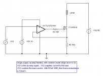
The normal way to include the FET in the feedback loop is shown in the attached schematic (operation should be self evident). This is the standard 'test-book' method and works very well.
It is only a controlled current sink of course. If you want an accurate VCCS that can both sink and source current, then things are a bit more complicated.
It is only a controlled current sink of course. If you want an accurate VCCS that can both sink and source current, then things are a bit more complicated.
Attachments
- Status
- This old topic is closed. If you want to reopen this topic, contact a moderator using the "Report Post" button.