This may be a bit OT, but after looking around, it seemed to not fit in the least here.
One of the things I dread doing the most with some of my vintage audio equipment is replacing burnt out lamps. Not only do I have to nearly tear the entire front of the unit apart, but I also have occasional trouble finding the light lamp as far as voltage, size, and mount are concerned.
I think that I am going to start replacing the incandescent bulbs with LEDs. But this presents several issues. While LEDs seem to operate just fine on as little as 1 volt, many of these systems provide 6, 8, 12, or even 36 volts to the lamps, and usually it is AC. It would be enough to wire in some resistors, but I cannot predict on some of these systems just how it would affect other things wiring in a bunch of components like resistors and LEDs.
So what would be the best way to replace these bulbs with longer-lasting, more efficient LEDs with minimum impact on the rest of the system?
Here is a quick drawing I made of a couple of possible configurations. I think I'm on the right trail, but each one seems to affect the circuit in an adverse way. I also have some much more complex ones drawn out, but that is on paper and I would have to scan them in.
Thanks.
One of the things I dread doing the most with some of my vintage audio equipment is replacing burnt out lamps. Not only do I have to nearly tear the entire front of the unit apart, but I also have occasional trouble finding the light lamp as far as voltage, size, and mount are concerned.
I think that I am going to start replacing the incandescent bulbs with LEDs. But this presents several issues. While LEDs seem to operate just fine on as little as 1 volt, many of these systems provide 6, 8, 12, or even 36 volts to the lamps, and usually it is AC. It would be enough to wire in some resistors, but I cannot predict on some of these systems just how it would affect other things wiring in a bunch of components like resistors and LEDs.
So what would be the best way to replace these bulbs with longer-lasting, more efficient LEDs with minimum impact on the rest of the system?
Here is a quick drawing I made of a couple of possible configurations. I think I'm on the right trail, but each one seems to affect the circuit in an adverse way. I also have some much more complex ones drawn out, but that is on paper and I would have to scan them in.
An externally hosted image should be here but it was not working when we last tested it.
Thanks.
There are a number of issues to solve. First is the resistor needed to drop the input voltage to something the LED can use. Look for the LEDs with the lowest current requirement. This means the dropping resistor can be smaller, say 1/8 watt. Then you'll need to find a small LED T1 (3mm). Then if its AC you'll need diodes to prevent reverse voltages from getting to the LED.
I think its worthwhile to solder an LED with a diode and a
resistor in-line and heat shrink the whole thing and use it
as a lamp replacement. It will draw a lot less amps and outlast
the lamp. Especially true for tube amps where the lamp
probably outdraws small signal tube plate currents.
I have extra LEDs if you want to experiment - LMK.
Bob
Parallel LEDs
Each LED in parallel requires a separate dropping resistor. LEDS do not all have the same forward voltage drop and if you parallel them directly, the one with the lowest forward voltage drop will hog all the current. It is better with multiple LEDs to have them in series, specially if you have loads of voltage to run them, which it appears you do. With an AC source, use two strings of series LEDs in inverse parallel and you can get away with a single dropping resistor.
Note that you must have some sort of inverse parallel diode, either another LED or something like a 1N4001 because LEDs cannot tolerate very much reverse polarity voltage, only about 3V each. By having inverse parallel series strings, the two strings protect each other.
Also note that LEDs do not have the dispersion of incandescent lamps and you will need a lot more. Myself, I find if you replace the incandescent lamps with new ones and put a dropping diode in series with them, while they will be dimmer and slightly yellow, they will last 5 times longer than before.
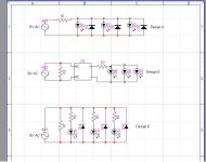
Well, I've taken in to consideration what you guys mentioned and here are a couple more schematics I came up with.
In designs 5 and 6, R3 and R7 (respectively) are there so that the AC source "sees" the same load as three bulbs wired in parallel (or does it matter?).
Design 5 is the simplest and seems to get the job done, but I don't know how wild I am rectifying the voltage at this point in the circuit (or, again, does it matter?).
I am using white LEDs, and I will be mounting them so they point at the diffuser.
------
I just noticed a potential problem with design 6, as D14, D15, and D16, as they are, could cause some problems. I would wire in a resistor in series with them of the same value as is used with the LEDs; also, I'm removing R7 (it seems like a waste of power...).
Attachments
OK, let's get more technical. A standard white led has a typical forward voltage of 3.7V @ 20mA, which is about the maximum current safe for an unknown white.
As said, one series resistor per string to prevent current hogging and uneven illumination. To calculate the resistor,
R = (Supply Voltage - Led Forward Voltage) / Led current
(Picking the nearest standard value up)
For series LEDs, just add the Vfs, ideally the total Vf should be under 80% of the nominal supply volts to allow room for variation.
For AC, the options are a series rectifier diode (to block reverse voltage) or an inverse parallel rectifier or second LED (to bypass reverse voltage). If you're hypersensitive to 50/60Hz flicker, a bridge could be used.
For mains level AC, a cap is generally used (0.47uF for 60Hz 110V, 0.33uF for 50Hz 230V) to drop most of the voltage, with a 1k 1W series resistor to limit switch-on charge current in the circuit. Less total heat produced than dropping all the spare volts with a resistor.
You can diffuse the light better if so required by roughening up the led surface with sandpaper/emery.
Should add that with half-wave rectified AC or inverse-parallel leds you can safely double the led current over the spec DC figures.
Wondering if somebody on here can help me determine exactly what resistors/diodes to add to the circuit of a Yamaha A-760II when replacing its four incandescent bulbs with white LEDs.
I have a schematic for the unit and I can solder but I'm not well versed in electronics so I can't read it reliably.
The bulbs that were in the machine are 8V 150mA and they must be in series because when one bulb burns out they all cease to work. (Though I don't exactly understand how they can be in series if each bulb turns on and off separately as an indicator for a corresponding front-panel switch.) The leads of each lamp go to two pins on a circuit board (so there are 8 pins on this one circuit board that are for the lamps.) My understanding from reading up online about other Yamaha amps of this period is that the current going to bulbs is AC and would need to be converted to DC using a Diode.
I have 5mm warm white LEDs rated at 3.2V 20mA — can anyone tell me (with a mathematical explanation) which resistors and diodes to use? Do I put one resistor and one diode before each LED?
Agvo,
If you have 3.2 V LEDs rated at 20 mA, then you could have 2 LEDs, a resistor, and a rectifying diode such as a 1n4001 in series. The two LEDs will drop 2 x 3.2 V and the rectifying diode about .7 V.
So, 8V - (2x3.2V + .7V) = .9 V across the resistor. Since you want 20mA, you can calculate the resistor value using Ohm's Law.
V=I*R
R = V/I = .9 V / .02 A = 45 Ohms
This would be for each of the 4 bulbs you are replacing.
Note that 20mA is probably the maximum rating for the LED and white LEDs can be pretty bright. You may end up wanting to use a higher value resistor to keep it from being too bright.
Thanks for the quick response radioFlash
Still not quite understanding a few things. If each LED is wired to two pins on the circuit board, I can't physically put two LEDs in series. (Though as I explained I think they're in series on the circuit board, but I can't read the schematic to find out how that works.)
So would I go from the positive pin on the board to a resistor, then a diode, then the LED, then back to the board? And do this for each separate LED? How would this change the value of the resistors/diodes?
Thanks in advance!!
...
So would I go from the positive pin on the board to a resistor, then a diode, then the LED, then back to the board? And do this for each separate LED? How would this change the value of the resistors/diodes?
Yes, I think you could do this. However, you said you thought power was AC, so there wouldn't be a positive pin on the board. You should get a multimeter and measure what voltage is coming from the board and verify it is AC or DC.
If you had just one LED and the rectifying diode you would have 3.2V + .7V = 3.9 V, leaving 4.1 V to be dropped by the resistor. You would need a 205 ohm resistor to give 20 mA in that case. I would probably experiment with resistor size and start with 1k and start moving lower if it's too dim.
Hi:
I recently replaced incandescent lamps with LEDs in several NAD receivers. I used the "three LED strips" avail cheap from ebay (see below). Receiver lamp supply was 12v. AC or DC? Don't recall! Prob DC.
These very compact strips have three surface mount LEDs (pick your color) and a current limiting resistor only. 12VDC spec. As mentioned above, LEDs must be "aimed" with a bit of care to illuminate the LCD or whatever you are lighting.
I understand a bit abt LEDs and AC v DC. I also tried attaching several of these strips to a (nominal) 12VAC typical outdoor lighting system. AC voltage at LED connection points ranged from ~8-12VAC. All the strips work fine after 100 hours or so.
The strips seem very versatile, cheap and adaptable to refurbing electronics. An additional current limiting resistor can b easily added if your supply is too hot.
diz
10 x 3528 SMD 3 LED Strip Lights DC 12V You Pick Colors Red, White, Blue or Mix
- Status
- This old topic is closed. If you want to reopen this topic, contact a moderator using the "Report Post" button.
- Home
- Amplifiers
- Solid State
- Replacing incandescent lamps with LEDs.