My Leach amp is now finished,so i take a few shots to share it with all you,who helped me and those who read this forum.
Amp have classic PCB design and i used only Motorola devices (ON),capacitors are not mica;in my country i cant find them so i use quality multylayer or ceramic caps.Amp casing was not planed i just go along and add things,as you see casing is built by Prof. Leach recomendation.(added bottom plate,25mm tick for robust look).Inbus screws adds more DIY look.Casing is made by soldering copper with 100W soldering iron.Classic design,on next project-class A more exotic housing design.
As i type this words,amp is richer by ALPS blue line pot and nice VU-meter(not yet built on these photos).This upgrade is probaly final.
Specs:-weight:15Kg total
-500VA,2x42V toroid
-6x10000uF caps total
-gold plated chinch inputs-must have these
-all metal parts are groundet to central ground point
Speakers are cheap type,made by me(german people probaly know Westra drivers)but take almost anything,like 150W amp and 100W speakers work just fine.Sure you must have good crossover.
A few words for each photo:
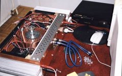
Photo1:
You see my DIY interconnect cables,on top right my new Marantz CD player,In the amp you see my transformer shield(probaly dont need one,but sure looks fine Above shielding is clearly seen CGP(central ground point)
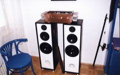
Photo2:
Amp,speakers-DIY,fishing gear and what is this black thing between speakers?
Is bad photo,but who gets even close i buy him Heineken beer
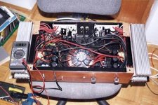
Photo3
Amp insides while measuring bias current.Heat sinks i got for free predrilled,once used for some kind industrial transistors.All amps components is screwed to wood(painted black),to give extra safety and for easy mounting.Left knob was peek indikator,removed instead i built VU-meter.
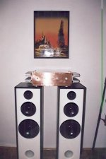
Photo4
Not wery good picture,amp was polished and flash did the rest.Dumb automatic,light was just right but stupid flash turned on.Whatever...
And at the end the most important thing(this is primary cause for writing this post)-Credits
Big thanks goes to:
Klas Mälman-his copper housing is just wonderful,and he help me a lot with ansvers.
Prof. Marshall Leach-solved power supply problems.
Vili Jan-my local PCB supplier.
Swede...and all i forgot.
Feel free to post your comments,good or bad dont matter.
My next project?Maybe class A,who knows...
Photo1
Photo2
Photo3
Photo4
Amp have classic PCB design and i used only Motorola devices (ON),capacitors are not mica;in my country i cant find them so i use quality multylayer or ceramic caps.Amp casing was not planed i just go along and add things,as you see casing is built by Prof. Leach recomendation.(added bottom plate,25mm tick for robust look).Inbus screws adds more DIY look.Casing is made by soldering copper with 100W soldering iron.Classic design,on next project-class A more exotic housing design.
As i type this words,amp is richer by ALPS blue line pot and nice VU-meter(not yet built on these photos).This upgrade is probaly final.
Specs:-weight:15Kg total
-500VA,2x42V toroid
-6x10000uF caps total
-gold plated chinch inputs-must have these
-all metal parts are groundet to central ground point
Speakers are cheap type,made by me(german people probaly know Westra drivers)but take almost anything,like 150W amp and 100W speakers work just fine.Sure you must have good crossover.
A few words for each photo:
Photo1:
You see my DIY interconnect cables,on top right my new Marantz CD player,In the amp you see my transformer shield(probaly dont need one,but sure looks fine
Above shielding is clearly seen CGP(central ground point)Photo2:
Amp,speakers-DIY,fishing gear and what is this black thing between speakers?
Is bad photo,but who gets even close i buy him Heineken beer
Photo3
Amp insides while measuring bias current.Heat sinks i got for free predrilled,once used for some kind industrial transistors.All amps components is screwed to wood(painted black),to give extra safety and for easy mounting.Left knob was peek indikator,removed instead i built VU-meter.
Photo4
Not wery good picture,amp was polished and flash did the rest.Dumb automatic,light was just right but stupid flash turned on.Whatever...
And at the end the most important thing(this is primary cause for writing this post)-Credits
Big thanks goes to:
Klas Mälman-his copper housing is just wonderful,and he help me a lot with ansvers.
Prof. Marshall Leach-solved power supply problems.
Vili Jan-my local PCB supplier.
Swede...and all i forgot.
Feel free to post your comments,good or bad dont matter.
My next project?Maybe class A,who knows...
Photo1
An externally hosted image should be here but it was not working when we last tested it.
Photo2
An externally hosted image should be here but it was not working when we last tested it.
Photo3
An externally hosted image should be here but it was not working when we last tested it.
Photo4
An externally hosted image should be here but it was not working when we last tested it.
Hello Igor!
Sorry to say that i cant se any pictures.... It looks like those images is linked to your local machine(on volja.net), instead of beeing attached to the forum....
Make another try to post them...
Looking forward to see the pictures...
Anyway, thanks for the creds... =)
/Klas
Sorry to say that i cant se any pictures.... It looks like those images is linked to your local machine(on volja.net), instead of beeing attached to the forum....
Make another try to post them...
Looking forward to see the pictures...
Anyway, thanks for the creds... =)
/Klas
shadow, why have you shielded the toroide with copper? Isn't it more sensible to use a magnetic material in order to shield magnetic field? I think it's looks nice with copper though.
(... and of course....you have isolated the bult from the copper...otherwise big problems for those who don't know)
(... and of course....you have isolated the bult from the copper...otherwise big problems for those who don't know)
Nice work Igor!
it look's great!
Are you satisfied with the sound ???
I raise the same concern as Peranders, and from the look of it it seams that the groundpoint is thetopside of the fasteningbolt of the transformer....
This means that your groudpoint is not at the same potential as the case...
This bolt actually becomes a separate winding of the transformer, about one halv turn.... Ie the topside of the bolt is moving in voltage in refernce to the bottomside of it.....
I have a friend who built a amp with two transformers and used centrumbolts to fasten those and a rail that was mounted on top of these.... This meant that there was a closed circuit of quite good conducting area formed by the bolts, the chassi and the bar.
We had truble understanding why the fuses blew if he had the primarys winded one way until we realised what was going on... , by shifting phase of one transformer primary the problem was solved.....
(What happened was that the bolts and the rail created a shortcicued winding through the two transformes.., by changing phase, the transformes are now working in phase with eachoter instead beeing shortcircued by eachoter...)
Keep the good work up!
Whats up next??
/Klas
Sound is great and central ground point is connected to case.I just have separate wire connecting CGP to case.Heatsinks and almost everything metal is connected to CGP.
I must take photos now...nice VU meter with blue light.
That metal thing between speakers...russian heavy cannon,antiaircraft,12mm caliber...nice huh?
Next...probaly class A.
I must take photos now...nice VU meter with blue light.
That metal thing between speakers...russian heavy cannon,antiaircraft,12mm caliber...nice huh?
Next...probaly class A.
peranders said:shadow, why have you shielded the toroid with copper? Isn't it more sensible to use a magnetic material in order to shield magnetic field? I think it's looks nice with copper though.
If you want to shield a steady magnetic field then use iron or mumetal or some other ferrous stuff. However, if you want to shield a varying magnetic field such as might come out of an EI transformer, use metal that has good electrical conductivity e.g. copper. The stray field induces current into the copper, this current has it's own field which then opposes the stray field. Something like that. Ask Mr Lenz and his Law. Anyway, iron for fixed fields, copper for AC fields.
Also, single point earth is great, but not through transformer hole. There will be a voltage difference between chassis and the top of the bolt.
GP.
- Status
- This old topic is closed. If you want to reopen this topic, contact a moderator using the "Report Post" button.
- Home
- Amplifiers
- Solid State
- My Leach amp,take a look