All constructive & critical comments welcome !
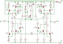
In my effort to design a class A amplifier, without following the usual well worn tracks, I came up with the attached design (follower). I do not recall seeing an 'exactly similar' (!!) circuit, especially the biasing arrangement and the measurement of supply current (Alexander amp ?), but if you know of something similar (that is not listed below) please let me know. I am not claiming some magical performance from this circuit (I don't have the equipment to measure this - yet) but I can see some possible advantages :
(1) single rail supply operating in constant current, can also use low voltage supply caps
(2) minimise the requirements for SOAR and Vce on O/P transistors, maybe more beta too ?
(3) self protecting output stage, as the current sources limit the dissipation (not tested yet !)
The examples I have built, so far, have exibited a strong tendancy to oscillate & ring (25MHz region), this seems to be mostly due to the emitter followers and can be reduced with base stoppers. All of my prototypes have very poor build quality in common (I must try harder !) so this could also be down to parasitic capasitance. The current source does not seem to want to oscillate, although it could be at the root of the ringing I am still seeing. Time will tell ...
Notes
(1 )I hope I transcribed the working circuit properly, but some extra components are shown on the schematic (R 25/26/27) that do not exist on the real thing.
(2) A variant, aimed at reducing the Vbe error without feedback, is hinted at on the schematic. My aim is to make the Vbe error in Q5 be cancelled by Q8 and the error in Q1 be cancelled by Q9. Remove R9/21/22/24/ and join Q8e to Q7c and the same on the other side. I have not tried this !!
(3) I am currently running the circuit at 1.5A total - this give approx 4w RMS into 12ohm (sub-optimal). I have run this up to 3A bias but my heatsink is really cooking so I do my testing at 1.5A
(4) Influences (the ones I can remember) : JLH class A, Alexander amp, Aleph, Aleph-X, plus some Op-Amp schematics (don't remember which), NP's various threads / circuits on Su-Sy
enjoy, dave
Attachments
And finally ...
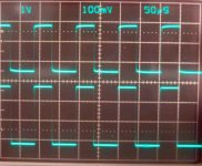
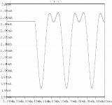
10Khz square (ish) wave, in and out.
Note, the diff amps are 1MHz bandwith (tek 7A22's) so you can't see the ringing
edit
Oops, forgot to mention that the scope trace also includes my x150 differential amp (no global feedback) plus an input attenuator - this explains the scaling.
dave
10Khz square (ish) wave, in and out.
Note, the diff amps are 1MHz bandwith (tek 7A22's) so you can't see the ringing
edit
Oops, forgot to mention that the scope trace also includes my x150 differential amp (no global feedback) plus an input attenuator - this explains the scaling.
dave
Attachments
I like it, and will use it, your assembling
I adequate to make tests, not loosing too much time to make beauty to shown others.
Good to the ears is enough.
When satisfied, put it another assembly, this way to satisfy your own eyes.]
Deep strong congratulations, specially because you avoid loose time to make show up!
regards,
Carlos
I adequate to make tests, not loosing too much time to make beauty to shown others.
Good to the ears is enough.
When satisfied, put it another assembly, this way to satisfy your own eyes.]
Deep strong congratulations, specially because you avoid loose time to make show up!
regards,
Carlos
Simply cool !
Especially the "cross symetric differential" biasing..
Strange but somehow faszinating.

Don't mind about your wild mechanical set up.
Often nice looking layouts are poor, because designed
for nice looking, instead electrical fortunate properties.
So if you take care about short wires and small loops at the right place, then such wild designs are perfect.... except reliability...
By the way:
How does it sound????
Bye
Markus
Especially the "cross symetric differential" biasing..
Strange but somehow faszinating.
Don't mind about your wild mechanical set up.
Often nice looking layouts are poor, because designed
for nice looking, instead electrical fortunate properties.
So if you take care about short wires and small loops at the right place, then such wild designs are perfect.... except reliability...
By the way:
How does it sound????
Bye
Markus
Now another good example, Mr Chocoholic made wonderfull amp.
But i am sure all the things start in a mass way, because no good expend time to make tests.... if no good, all time to trash!
You can see Chocoholic works, clean, pretty, well done.... but i am sure he did not started his own design this way.
I can see many people making better than factories, better than industries..... why?, if not to sale!, only for show!
In my country we have a said, related those things (hahahaha)
"If you want to appear, switch on 2 or three spot lights over and around your body, and can put something alike a watermellow in pieces around the neck, as collar, some bananas inside the hairs and nude will be better to call yourself the attention."....hohohoho
You do not need that, this way, again, congratulations
Carlos
Thank you for the comments
Thank you for the comments,
I am sorry about the delay in responding, but I was enjoying some half-decent sunshine here in the UK – probably very tame compared to Israel or Brazil but quite similar to Germany?
SS, the output of this circuit does have some ringing at high amplitudes, but my wideband 'scope amplifier was faulty when I did this (just one more thing for me to fix) - also this is into a real loudspeaker load and my neighbours (and their dogs) do not have infinite patience for full power (all 4w RMS of it) !!
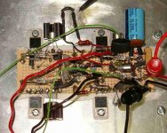
destroyer-X, the 'punchboard and pins' technique is quick to assemble but, with the example shown, I made the circuit board too small making experimental changes very difficult. I made the same mistake on a previous prototype which 'smoked' and was too difficult to repair. It is unfortunate for me that my best efforts, despite guidance from expert technicians in the (distant) past, doesn't look much better but at least it does usually work (at least for a while) ! Maybe I should try the technique you described in the past (with the small squares of copper clad) ...
ChocoHolic, yes, I think this is a good description of the biasing. I drew the circuit before I thought of it (if that makes any sense - I was drawing lots of variants) and it took quite a while before I convinced myself that it might actually work as an amplifier ! Have you seen anything similar before? I cannot tell much about sound quality with the setup I have at the moment - the 4 inch speakers (used as full range) I am using sound rather rough above 5KHz giving the sound a bit of a 'honk'. The total lack of bass (as there in no baffle) doesn't help either. Other than this, the sound is quite reasonable - percussion instruments sounding particularly good.
Best I can measure at the moment it that the 2nd/3rd harmonics are below -55db at 90% power (I was expecting -60db due to the Vbe errors but my estimates could be totally wrong) but these figures do include the 150 gain voltage amp (no feedback yet - but that's another story) and the 'scope diff amps / frame.
Thank you for the comments,
I am sorry about the delay in responding, but I was enjoying some half-decent sunshine here in the UK – probably very tame compared to Israel or Brazil but quite similar to Germany?
SS, the output of this circuit does have some ringing at high amplitudes, but my wideband 'scope amplifier was faulty when I did this (just one more thing for me to fix) - also this is into a real loudspeaker load and my neighbours (and their dogs) do not have infinite patience for full power (all 4w RMS of it) !!
destroyer-X, the 'punchboard and pins' technique is quick to assemble but, with the example shown, I made the circuit board too small making experimental changes very difficult. I made the same mistake on a previous prototype which 'smoked' and was too difficult to repair. It is unfortunate for me that my best efforts, despite guidance from expert technicians in the (distant) past, doesn't look much better
but at least it does usually work (at least for a while) ! Maybe I should try the technique you described in the past (with the small squares of copper clad) ...ChocoHolic, yes, I think this is a good description of the biasing. I drew the circuit before I thought of it (if that makes any sense - I was drawing lots of variants) and it took quite a while before I convinced myself that it might actually work as an amplifier ! Have you seen anything similar before? I cannot tell much about sound quality with the setup I have at the moment - the 4 inch speakers (used as full range) I am using sound rather rough above 5KHz giving the sound a bit of a 'honk'. The total lack of bass (as there in no baffle) doesn't help either. Other than this, the sound is quite reasonable - percussion instruments sounding particularly good.
Best I can measure at the moment it that the 2nd/3rd harmonics are below -55db at 90% power (I was expecting -60db due to the Vbe errors but my estimates could be totally wrong) but these figures do include the 150 gain voltage amp (no feedback yet - but that's another story) and the 'scope diff amps / frame.
Hi Dave!
...for me this biasing is new...
Who said: "Nothing new under the sun." ???
markp?
http://www.diyaudio.com/forums/showthread.php?s=&threadid=36348&highlight=
IMHO -55db distorsion is not bad for a zero feedback voltage follower.
Bye
Markus
...for me this biasing is new...
Who said: "Nothing new under the sun." ???
markp?
http://www.diyaudio.com/forums/showthread.php?s=&threadid=36348&highlight=
IMHO -55db distorsion is not bad for a zero feedback voltage follower.
Bye
Markus
Yep, it was me. Of course, I wasn't the first nor the last to use that line.ChocoHolic said:Hi Dave!
...for me this biasing is new...
Who said: "Nothing new under the sun." ???
markp?
http://www.diyaudio.com/forums/showthread.php?s=&threadid=36348&highlight=
IMHO -55db distorsion is not bad for a zero feedback voltage follower.
Bye
Markus
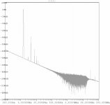
This looks UGLY !!
I've attached the current waveform in R25 / R26 (5KHz sinewave / max amplitude). These are the collector loads for the input differential. I think my outer differential loads the inner differential too much, or is there some other explaination Maybe I should have stuck to 2 common emitters here ? Should I be bothered about this wierd waveform anyway
I've attached the current waveform in R25 / R26 (5KHz sinewave / max amplitude). These are the collector loads for the input differential. I think my outer differential loads the inner differential too much, or is there some other explaination
Maybe I should have stuck to 2 common emitters here ? Should I be bothered about this wierd waveform anyway Attachments
- Status
- This old topic is closed. If you want to reopen this topic, contact a moderator using the "Report Post" button.
- Home
- Amplifiers
- Solid State
- Comments please, on my class A follower