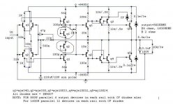
I am trying to change this amp a bit but I need some help to make sure I do it right not twice .I have changed the output transisotrs from npn on both sides(npn.jpg) to npn on - side and pnp on + side and what do the cf diodes do can i get rid of them with no problems and are the transistors i have marked the ones that control thermal runaway.and also more volts but I dont think this will be a problem can anyone tell me if I have it correct or not will it work
Attachments
Hi !
Are you sure, that you want increase the voltagesupply from
94v to 120v ? This will change all biasing, unless you adapt
some resistors. (like the 30k to 38.3k)
And you will push the mje15032/33 to its absolute limit of 250v.
You could use mje15034/35 instead.
But the mj15024 output still has a 250v limit, and theres no
substitute in this family with higher voltageratings.
And i think you should skip the 12e-resistor at collector of q3.
When building the amp, you should match the mje340/350 pairs,
these are rated with a hFe 30 - 240. If you use that different
transistors in the VAS or Diffamp, you will get big problems.
http://www.onsemi.com/site/products/summary/0,4450,MJE340,00.html
Michael
Hi wonder!
Yes, the marked transistors are for thermal compensation.
But if you want to go for a symmetrical npn/pnp outputstage, then I would strongly recommend the following:
-Towards the positive rail keep npn for q5 and CF as it was in the original schematic. CF diode provides a current feedback at high output currents and will limit the output current in case of overload or short circuit.
-Towards the negative supply use a pnp type in the symmetrical way and also but the diode.
- If you go for a higher rail, you should keep some reasonable margin against max. rating. About 100V would be enough for my taste.
Already then you should increase the 0.1 Ohms to 0.12 Ohms as
with higher currents you must limit at lower current values.
And also take care about the changed biasing of all stages at higher supply as Michael already stated.
... I will modify your schematic to show what I mean....
Cheers Markus
MikeB said:
But the mj15024 output still has a 250v limit, and theres no
substitute in this family with higher voltageratings.
Michael
Ofcourse Micheal, but the Mj21195/96 will give much better SOAR therefore better reliability at high voltages... right?
As for family of devices, the MJL4302 and MJL4381 are same family (albeit in T-O3PL pack) i.e. Powerbase power transistors and have VCE ratings of 350v. Then again you will need many in paralell...
")
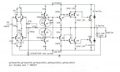
OK, it looks like that the diode CF is put in order to enable higher output voltage swing.
Without diode CF the 12 ohms emitter resistor of q3 would limit
the max. output swing at a remarkable value below the rails, if high output current is drawn. If CF is placed then q3 can draw it's current
also through the diode CF and will be able to allow an output swing close to the rails.
Nevertheless I would recommend to arrange the npn at the positive rail and the pnp at the negative rail for this circuit as shown in my attached image.
Attachments
just checked the image "wonder.jpg":
Please note that some information was cut
For q4 there is missing the 4.
For the emitter resistor of q4 should be 12 Ohms, somehow
the 2 has been deleted/covered.....
Nevertheless I hope that it worked out to convey, that I would
arrange the npn and pnp transistors in the opposite way as you had proposed.
Did you have a special reason for your arrangement?
Bye
Markus
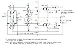
the outputs transistors each have there own emitter resistors the drive transistors do not but one on each side should be enough for 8 output transistors on each side but when you got a box of them why not two and it leaves room to go to 2ohm load 16 output transistors p/s later on .If you think the drive transistors need emitter resistors plz tell me
UPUPA can you post a pic of serial connection of output transistors I have herd of this but never seen it and I dont know how to go about making this kind of thing
also to stop speaker wires from shorting or zaping someone with this kind of voltage I am going to put 2 pin plugs (sim to jap 110v power plugs)on the speaker outputs it will also have fuses somewhere on the outputs (not in schimatic yet)
also to stop speaker wires from shorting or zaping someone with this kind of voltage I am going to put 2 pin plugs (sim to jap 110v power plugs)on the speaker outputs it will also have fuses somewhere on the outputs (not in schimatic yet)
I could not make this amplifier work.
In Simulation i found deep unballance.... and when this happens, real world assembling always fail.
I have no knowledge to help you... this way.... i will be out of this thread to open space to people with better knowledge to help you.
Thanks Choco to came to help this guy, that's second time i tried and failled.... he insists in this amplifier....i suppose he do not want another.....maybe he has already the supply.
This way...bye and good luck, i will came hear from time to time to see if someone gave solution...put this schematic to work.... i think it is wrong... i could not see where... i change a lot to ballance....could not.
When started to be stable....is another amp...not more Mr.Wonder circuit... this way.... making another is easy..... hard is to make this one to work!
Regards all
Carlos (running out this amp)
K-amps said:
Ofcourse Micheal, but the Mj21195/96 will give much better SOAR therefore better reliability at high voltages... right?
As for family of devices, the MJL4302 and MJL4381 are same family (albeit in T-O3PL pack) i.e. Powerbase power transistors and have VCE ratings of 350v. Then again you will need many in paralell...
Yes, the mj21195/96 have better SOAR, but from what i have learned,
you shouldn't use transistors that close to their limit, they might
sound bad. In addition you shouldn't forget the reactive loads from
speakers, especially the inductive load can add several volts, moving
the transistor out of the limit. (You might reduce this problem with
some diodes)
Hmm, the MJL4302 and MJL4381 are not the same family, they have
an fT of 30Mhz, the mj15024 has only 4mHz. (by the way, the 15024
is TO3)
You shouldn't replace transistors with some completely different
types without adjusting the whole amp to the new bandwidth.
This will change the sound and stability.
But this kind of modification seems to me the most difficult part
in designing an amp.
Michael
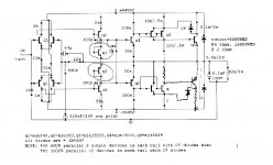
paralleled driver bipolars
Hi Wonder!
Also in the driver transistors you will get unbalanced current sharing if you parallel them without emitter resistors.
If you know that one would be sufficient, then you will not need the second in parallel. If you have doubts, or just want some margin against the limit, and want to use two in parallel, then you should use the emitter resistors. If you use two paralleled bipolars without emitter resistors, then it can happen that one transistor may carry 80% of the load and the other only 20% and you would not get much advantage of the second.
By the way: I agree to Mike that oscillation is a difficult thing.
Different transistor types can really cause issues.
Also it can be a difference if you have one or two driver transistors parallel.
Besides correct frequency compensation (adjusting both capacitors between base and collector in the VAS & may be the cap across the feed back resistor)... Besides this, there is an important that seems to be ignored sometimes. The DC rails must have blocking caps close to the output transistor. A good configuration in my experiments was always the following: For each pair of output transistors put two capacitors (in the range 33uF ...150uF). These two capapcitors are connected in series and placed close to the transistors from positive rail to negative rail. The center tap of both capacitors has a connection to the ground of the circuit.
Still for my taste that high rail voltage is to close to the limits.
....voltage rating and SOAR....
Series connection is more difficult....
My feeling:
It does not make sense to squeeze the last Watt out of an overlaoded design.
If we compare 120V rails and 110V rails then the 120V will allow about 20% more output power. That's 1.5db. Marginal difference for our ears, but big difference in reliability!
Bye
Markus
- Status
- This old topic is closed. If you want to reopen this topic, contact a moderator using the "Report Post" button.
- Home
- Amplifiers
- Solid State
- I need help with this amp