Slew rate: Nothings free.
Don't forget CFAs, rather, understand their subtleties as one day a requirement will come along where such a cfa will be superior.
My 2 cents.
Thanks
-Antonio
Out of curiosity, I did a comparative simulation of a VFA and a so called 'CFA' input stage. Provided that the CFA stage is correctly configured and provided that the trannies are truly complementary (not possible in real life), the CFA stage produced 2000 times less distortion.
One more 2 cents.
Cheers,
E.
Good to know that! However, since a truly complementary is non-existed in real life a study of the distortion behavior over trannie mismatching between VFA and so-called CFA might give more insight. Thanks for the two cents, unfortunately in good old Canada, the pennies has recently been discontinued of being a legal tender, no longer can one cash a penny here in real life any more, though we do see it in papers such as our bills and government notice about taxes we owe
") .
.Out of curiosity, I did a comparative simulation of a VFA and a so called 'CFA' input stage. Provided that the CFA stage is correctly configured and provided that the trannies are truly complementary (not possible in real life), the CFA stage produced 2000 times less distortion.
One more 2 cents.
Cheers,
E.
Hi Edmond, could you show simulated amps circuit? In my simulations I've got just opposite, must be that I do something wrong.
BR Damir
Okay
Cheers,
E.
This is not fair comparison. As CFA you use current conveyor and ideal output stage(as in VFA), but a current conveyor is very load sensitive and with real output stage VFA will produce lower distortion(at least in all my simulation attempts).
BR Damir
Out of curiosity, I did a comparative simulation of a VFA and a so called 'CFA' input stage. Provided that the CFA stage is correctly configured and provided that the trannies are truly complementary (not possible in real life), the CFA stage produced 2000 times less distortion.
Yes, but with less open loop gain available, significant nonlinearities elsewhere in the path really kills. Really evident making changing an ideal voltage follower have a nonlinear term.
As far as mismatching I typically start with an ideal transistor set of parameters ie IS={IS} BF={BF} CJE={CJE}, common between npn and pnp transistors except that one set has an additional multiplier M so these parameters look like IS={M*IS}, BF={M*BF} etc. Typically will add reality to parameters one or a few at a time, then add mismatching.
I was actually surprised how much mismatch was allowed before reaching the same level of distortion.
I've been fasinated by the subtle differences in the i-v curves of the input transistors between cfa and vfa or voltage steering versus current steering.
Thanks
-Antonio
the CFA stage produced 2000 times less distortion.
.
Three orders of magnitude is a lot, too much in fact.
Once you have extracted the available gain NFB is the only thing
that will reduce non linearities , so either there s tremendously
higher OLG , or way better linearity to start with , wich is not
possible given that it s the same active components.
This is not fair comparison. As CFA you use current conveyor and ideal output stage(as in VFA), but a current conveyor is very load sensitive and with real output stage VFA will produce lower distortion(at least in all my simulation attempts).
BR Damir
Hi Damir,
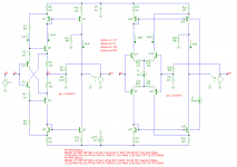
Why it is not a fair comparison? I'm only comparing the two input stages. The rest is kept the same. Whether it's a real amplifier or not, doesn't matter. It's just a test circuit where the input trannies operate under the same conditions (i.e. same trans-conductance and same ratio between AC current vs idle DC current).
Cheers,
E.
Maybe not, but it is certainly useful to prove the potential (very) high slew rate of CFAs. That is, the "current on demand" property.
Yes, tha is what I meant. Of course the feedback resistors set the closed loop gain - so no discussion there.
I still do not see these things as being equivalent ( i.e. in topological terms) to VFA and prefer to see the feedback as being of the current type. The fact that the gain equation reduces to the same form as that for a VFA should not lead one to abandon the current feedback view. (Kind of like those 2 economists that used math to prove their theories, win the Nobel prize for economics - a misnomer in itself - go out and start an investment company, fail miserably. Someone then points out that their whole theory was based on the wrong premise. Then there was the one that was famously criticized for not using enough math, but seems to have got his theory right.)
I still do not see these things as being equivalent ( i.e. in topological terms) to VFA and prefer to see the feedback as being of the current type.
No problem, it's your call to build a fence and place yourself on one side.
I prefer, if possible, a world with less fences, fences obstruct the view and usually require defense (like in the current debate).
there seems to be an old assumption that good compliments cannot/do not exist in IC opamps. That used to be the case a long time ago, but processes have evolved and in fact the CFA couldnt be made until proccesses were developed to make good compliments. They exist just fine in todays high speed CMFB opamps.
Its just too bad for the DIY'er that such complimentary devices are not available in simple pairs to us.
Thx-RNMarsh
Its just too bad for the DIY'er that such complimentary devices are not available in simple pairs to us.
Thx-RNMarsh
Richard, you make a good point. However, for discrete designs I think the designer can still get some pretty good results with the available parts. For instance, you can get NPN and PNP pairs matched to with 2% hFE and Vbe from a number of vendors (in SMD packages - but still very solderable ). These are not the complimentary pairs you mention, but sorting through a batch I am sure would yield pairs of closely matching devices. In my two recent CFA design efforts nx-Amplifier: A 100 W class AB CFA Amplifier and Ovation sx-Amplifier I simply used high gain BC547C and BC557C types with good results. No doubt, carefull matching would yield better results, but I no longer have access to an AP to veryify the possible gains. They sound pretty damn fine though.
Most CFA power amps are going to use some form of emitter degeneration which will help mitigate some of the points raised earlier. If you make the assumption that power dissipation of the buffer stage is not a limiting factor (thermal considerations notwithstanding) as is the case of opamps, you can also run the whole thing hard into class A if thats your pursuasion. As Edmond has pointed out, the front end of a CFA can be optimized for very low distortion - I posted an LTSpice line stage design effort of mine up about 3 years ago that got me down into the low hundreds of ppb, and this was achieved with minimal effort (16dB gain, 2V out into 600 Ohms IIRC at 20 kHz). So, a number of us do not recognize CFA's as being poor performers -just different!
). These are not the complimentary pairs you mention, but sorting through a batch I am sure would yield pairs of closely matching devices. In my two recent CFA design efforts nx-Amplifier: A 100 W class AB CFA Amplifier and Ovation sx-Amplifier I simply used high gain BC547C and BC557C types with good results. No doubt, carefull matching would yield better results, but I no longer have access to an AP to veryify the possible gains. They sound pretty damn fine though. Most CFA power amps are going to use some form of emitter degeneration which will help mitigate some of the points raised earlier. If you make the assumption that power dissipation of the buffer stage is not a limiting factor (thermal considerations notwithstanding) as is the case of opamps, you can also run the whole thing hard into class A if thats your pursuasion. As Edmond has pointed out, the front end of a CFA can be optimized for very low distortion - I posted an LTSpice line stage design effort of mine up about 3 years ago that got me down into the low hundreds of ppb, and this was achieved with minimal effort (16dB gain, 2V out into 600 Ohms IIRC at 20 kHz). So, a number of us do not recognize CFA's as being poor performers -just different!
Last edited:
I dont know where the idea that cm circuits dont do well. Its a push-pull family and they do just fine. About 35 years ago, my little CFA idea was simple but had a thd+n that was below .0018%--- the lower limit of the HP test gear of the era. I had to run the little line amp up to +22 and -22v peak to peak to see it rise above that floor [used +/- 24vdc supplies]. Just hand matched a bunch of NPN and PNP on a curve tracer... still the best way. Oh and it used 20dB of fb.
I'd like to see a power amp using cmfb topology of about 450W/8 or more for my use at home. THD <.001%
No, really.
Thx-RNMarsh
I'd like to see a power amp using cmfb topology of about 450W/8 or more for my use at home. THD <.001%
No, really.
Thx-RNMarsh
Last edited:
Hi Damir,
Why it is not a fair comparison? I'm only comparing the two input stages. The rest is kept the same. Whether it's a real amplifier or not, doesn't matter. It's just a test circuit where the input trannies operate under the same conditions (i.e. same trans-conductance and same ratio between AC current vs idle DC current).
Cheers,
E.
Hi Edmond,
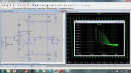
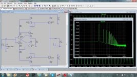
I simulated your input stage in two mode, as CFA and as pure current conveyor with no feedback, and difference in distortion is very small, 0.031589% for the CFA and 0.045572% for the CC.
My point is that a current conveyor has low distortion by itself and feed back will not improve it much.
Here are my simulations.
BR Damir
Attachments
Last edited:
I dont know where the idea that cm circuits dont do well. Its a push-pull family and they do just fine. About 35 years ago, my little CFA idea was simple but had a thd+n that was below .0018%--- the lower limit of the HP test gear of the era. I had to run the little line amp up to +22 and -22v peak to peak to see it rise above that floor [used +/- 24vdc supplies]. Just hand matched a bunch of NPN and PNP on a curve tracer... still the best way. Oh and it used 20dB of fb.
I'd like to see a power amp using cmfb topology of about 450W/8 or more for my use at home. THD <.001%
No, really.
Thx-RNMarsh
350 W is on the drawing board. With AFEC of course
- Status
- This old topic is closed. If you want to reopen this topic, contact a moderator using the "Report Post" button.
- Home
- Amplifiers
- Solid State
- Current feedback - Voltage feedback, how do I see the difference?