jcx said:there appears to be more technically succinct language(s) for this discussion:
http://people.ee.ethz.ch/~hps/publications/2000cas.pdf
ran across this while adding nordholt to search:
http://www.s2.chalmers.se/graduate/courses/analogVLSI/doc/lecture2.pdf
I don’t think the level of exchange we manage here is really getting at the subject matter
I am not sure about this JCX....it would appear this ground has already been covered here:
http://www.diyaudio.com/forums/showthread.php?postid=422719#post422719
http://www.diyaudio.com/forums/showthread.php?postid=425077#post425077
current feedback (alexander type)
Current feedback is independent of bandwith so it is interesting, using a opamp like in the schematic is a clever way to overcome tthe disadances of current feedback be low impedance, using a opamp as current suplier through its voltage pins.
Special the TIM is very low, this distortion gives music a very raw sounding character in most amps, it is the most important distortion, that have to be as low as possible, voltage feedback gives high TIM if not properly used and is why the most amps not giving open sound. as always feeback is the bad thing in tube world but is not always true, I have now a hybride without feedback, it sounds very good and open, but current feedback is also very nice sounding en fast...
A Paul Kemble web page - SSM 2131 (power amp design).
somehwere here i have posted a schematic with alexander thinking with whole bipolairs.
Last edited:
It is a current feedback amplifier when the feedback is applied to the emitter (cathode, source), because then the current of the feedback signal is added to (or subtracted from) the current of the input stage.
No: the shunt derived series applied feedback voltage is applied to the emmiter of the input stage and therefore subtracted from the input voltage apllied to its base.
That the current through the feedback network is non-negligible is irrelevant.
Last edited:
Phew! Glad that is settled. Finally. "It is fundamentally different in a major way".
A short study, sponsored by IEEE, on the subject can be obtained as a UK Oxford booklet produced in 1994 by Chris Toumazou, John Lidgey and Alison Payne.
"Emerging Techniques For High Frequency BJT Amplifier Design: A Current-Mode perspective".
-RNM
A short study, sponsored by IEEE, on the subject can be obtained as a UK Oxford booklet produced in 1994 by Chris Toumazou, John Lidgey and Alison Payne.
"Emerging Techniques For High Frequency BJT Amplifier Design: A Current-Mode perspective".
-RNM
Last edited:
No: the shunt derived series applied feedback voltage is applied to the emmiter of the input stage and therefore subtracted from the input voltage apllied to its base.
That the current through the feedback network is non-negligible is irrelevant.
I was always under the impression that there would be non-negligable current into a low-impedance (emitter) feedback node in a 'CFA' opamp. In that sense, I could understand where the term came from, even if it was completely opposite the terminology since the middle of last century.
But if you think about it, the node impedance may be low, but the current into it is also determined by the voltage difference between that node and the input. Feedback doing its job makes that voltage difference very, very small (zero in the limiting case of infinite feedback). I simmed a simple gain-of-10 amp with an AD844 and found that the current into the low-impedance (emitter) node was less than 500nA! Another perspective...
jan
This is probably the least necessary topic to revive. Go back to Middlebrook, you are not simply "sampling" the voltage at the input and there is significant current into the inverting input so "breaking the loop" is fundamentally different in a major way.
We are not sampling the voltage at the input. Rather, we have a voltage divider in parallel with the load sampling the voltage at the output, and, self evidently, not the output current.
The fraction of the output voltage dropped across the resistor in the voltage divider connected to ground is fed into the emitter of the input stage of the input device. The current through the divider is completely irrelevant.
Moreover, Middlebrook's method of section 5 in the paper below can be used in LTSpice at any point in the loop, so breaking the loop is not different in any way from that executed in a VFA which uses a differential pair for its input:
http://www.ele.tut.fi/teaching/ele-3100/lk0809/tehol1/MiddleBrook75.pdf
I was always under the impression that there would be non-negligable current into a low-impedance (emitter) feedback node in a 'CFA' opamp.
But all transistors are voltage controlled devices, so its the difference between the input voltage and the voltage at the emitter (or source as the case may be) that controls the device's collecter current (or drain current) in a so-called "CFA".
As noted above, the current through the voltage sampling divider is completely irrelevant as it does not drive the input transistor.
Also dont forget that a typical CFA input stage is symmetrical and thus the error current distortion or output voltage distortion is the difference between the distortion of the n and p side currents (and that these base emitter voltages divide equally, less effects from the error current).
Thanks
-Antonio
Thanks
-Antonio
The current through the divider is completely irrelevant.
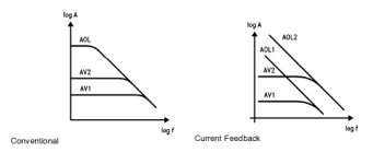
Mike this is just wrong. EE102 1969 series-shunt feedback, the classic example is the three npn video triple. Breaking the loop involves loading the inverting input with the feedback network, for a VFA this is almost irrelevant but for a CFA this varies the input transconductance with closed loop gain. The important properties then fall out. Your statement elsewhere that the open-loop GBW of a CFA is constant is also wrong. As you can see my esteemed colleagues from Texas agree (picture below). This view point only arises when the loop is simply broken at the inverting input and it is considered a voltage input point, this is simply not valid.
Folks find an EE text that introduces the four basic feedback configurations as two ports with Y parameters and see for yourself. I mentioned Middlebrook because his technique avoids these mistakes.
Attachments
But if you think about it, the node impedance may be low, but the current into it is also determined by the voltage difference between that node and the input. jan
Forcing zero voltage and zero current are the same thing. You can analyze a CFA by taking only the current in as the feedback signal and arrive at the same answer. Jan this stuff really is simple, just review forming the classic a/(1+af) equation for the different feedback configurations.
Last edited:
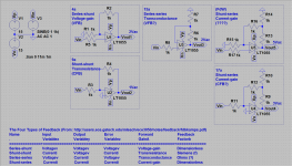
And here is my little contribution, based on this paper http://users.ece.gatech.edu/mleach/ece3050/notes/feedback/fdbkamps.pdf there are 4 configurations, all four to be found in the attached schema. Strangely enough (for me at the least) there is a 5th ") . My questions remain, how to call the 4 types, VFB, CFB, ... and it that really a 5th?
. My questions remain, how to call the 4 types, VFB, CFB, ... and it that really a 5th?
. My questions remain, how to call the 4 types, VFB, CFB, ... and it that really a 5th?Attachments
Last edited:
Mike this is just wrong. EE102 1969 series-shunt feedback, the classic example is the three npn video triple. Breaking the loop involves loading the inverting input with the feedback network, for a VFA this is almost irrelevant but for a CFA this varies the input transconductance with closed loop gain. The important properties then fall out. Your statement elsewhere that the open-loop GBW of a CFA is constant is also wrong. As you can see my esteemed colleagues from Texas agree (picture below). This view point only arises when the loop is simply broken at the inverting input and it is considered a voltage input point, this is simply not valid.
Folks find an EE text that introduces the four basic feedback configurations as two ports with Y parameters and see for yourself. I mentioned Middlebrook because his technique avoids these mistakes.
The variation shown in your diagrams is due to the fact that the basic gain equation of a common emitter stage is Rload/Remitter.
The input stage of a so-called "CFA" is a common emitter stage, and because the feedback voltage divider is returned to the emitter of this stage, the forward gain of the amplifier also changes as the resistors of the feedback network are changed.
As I've pointed out, this is the means by which the apparent bandwidth is changed.
Scott,
See fig 6 on pg 8 here:
http://users.ece.gatech.edu/mleach/ece3050/notes/feedback/fdbkamps.pdf
Also, read the text associated with this figure (section entitled "Transistor Example"); you should quickly realise that CFA is a complete misnomer, as it confirms everything I've said on the subject..
Note that the table 1 on pg 2 corresponds with my definitions here:
http://www.diyaudio.com/forums/soli...current-feedback-amplifier-8.html#post3414948
Last edited:
Forcing zero voltage and zero current are the same thing. You can analyze a CFA by taking only the current in as the feedback signal and arrive at the same answer. Jan this stuff really is simple, just review forming the classic a/(1+af) equation for the different feedback configurations.
Yeah sure it is simple, but sometimes you really need to think it through. Or at least I need to do it sometimes
jan
And here is my little contribution, based on this paper http://users.ece.gatech.edu/mleach/ece3050/notes/feedback/fdbkamps.pdf there are 4 configurations, all four to be found in the attached schema. Strangely enough (for me at the least) there is a 5th
Well, these are the 'official' gang of four
http://www.linearaudio.nl/linearaudio.nl/images/pdf/leach_feedback_basics.pdfDon't know about any 5th...
Edit: same link as Mike's... sorry.
Anyway, Mike, I believe you meant that emitter of the feedback node to be a common base stage, not a common emitter stage (from the pov of the feedback network).
jan
Last edited:
Anyway, Mike, I believe you meant that emitter of the feedback node to be a common base stage, not a common emitter stage (from the pov of the feedback network).
This is true from the point of view of the feedback network; this view point is necessary to establish whether your feedback network indeed delivers negative feedback (by signal tracing). See last sentance at the bottom of pg 8 and the top of pg 9 here:
http://users.ece.gatech.edu/mleach/ece3050/notes/feedback/fdbkamps.pdf
However, from the point of view of the input signal, the input device is a common emitter stage, merely amplifying the voltage difference between its base and its emitter.
Last edited:
Well, these are the 'official' gang of four
Don't know about any 5th...
Edit: same link as Mike's... sorry.
Well this is a bit of a strange reaction, it credits the link that I found to Mike and then ignores what I am asking (and remarking) completely. Maybe I was not clear enough, and do I need to explain myself a bit more.
All documentation that I can find talks about 4 models, as in the linked paper, but we (here at DiyAudio) are talking about CFB or VFB, can someone please explain how this reflect to the 4 models. In other words, what models are VFB and what models are CFB?
If these models are looked upon, one can see that if 9a(shunt-shunt) transforms 17a(shunt-series), as in the linked paper, then 4a(series-shunt) should transform into (FdW)(the 5th model). The question is, is this a just observation, and how should it be called, or where am I wrong?
As the tittle of the thread is 'Current feedback - Voltage feedback, how do I see the difference?'
I thought that a picture may say more than a thousand words, so a annotated picture might help a bit
Last edited:
Well this is a bit of a strange reaction, it credits the link that I found to Mike and then ignores what I am asking (and remarking) completely. Maybe I was not clear enough, and do I need to explain myself a bit more.
All documentation that I can find talks about 4 models, as in the linked paper, but we (here at DiyAudio) are talking about CFB or VFB, can someone please explain how this reflect to the 4 models. In other words, what models are VFB and what models are CFB?
If these models are looked upon, one can see that if 9a(shunt-shunt) transforms 17a(shunt-series), as in the linked paper, then 4a(series-shunt) should transform into (FdW)(the 5th model). The question is, is this a just observation, and how should it be called, or where am I wrong?
Sorry Frank, I wasn't crediting Mike with the link, but didn't see him putting it up before I put it up myself.
There's no correspondence between the four topologies and the CFB/VFB terminology. The four concepts concern itself with what you sample at the output (current or voltage) and how you add the feedback signal to the input signal (in series or shunt/parallel). The reason is that this immediately shows the effect on the amp: decreased or increased output Z, and increased or decreased input Z.
The CFB/VFB terminology came en vogue after Elantec designed the first opamps with a low-impedance (emitter) feedback node which had some favourable effects on the bandwidth and called it current feedback. Must have been late 70's? But it doesn't say anything about the effect of the feedback on the amp, because you can still use this 'CFA' with either current or voltage output sampling to make an amp with zero or infinite Zout.
So we're stuck with two different ways of looking at feedback, which have no correspondence.
jan
The input stage of a so-called "CFA" is a common emitter stage, and because the feedback voltage divider is returned to the emitter of this stage, the forward gain of the amplifier also changes as the resistors of the feedback network are changed.
As I've pointed out, this is the means by which the apparent bandwidth is changed.
This is half semantics, the behavior as a three terminal device is fundamentally different naming convention aside. The current that drives the gain node i.e. the Ccomp flows in the feedback network. Can you deny this (that's where the high slewrate comes from to)? In light of this I find the CF designation rather innocent.
The input stage of a so-called "CFA" is a common emitter stage, and because the feedback voltage divider is returned to the emitter of this stage, the forward gain of the amplifier also changes as the resistors of the feedback network are changed.
Except by equation 67 of that reference it wouldn't ???? Certainly the forward voltage gain of the first device looking from the non-inverting input (vs) to ground is not gmRc ????
Last edited:
- Status
- This old topic is closed. If you want to reopen this topic, contact a moderator using the "Report Post" button.
- Home
- Amplifiers
- Solid State
- Current feedback - Voltage feedback, how do I see the difference?