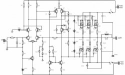
I have found this schematic on the web.
Is this a good amp? What do you think?
Item Label-Value Attributes Designation
1 220pF 100V RAD0.2 C1
2 33pF RAD0.2 C2
3 22pF 100V RAD0.2 C3
4 22pF 100V RAD0.2 C4
5 68nF 100V RAD0.3 C5
6 0.1uF 250V RAD0.4 C6
7 0.1uF 250V RAD0.4 C7
8 0.1uF 250V RAD0.4 C8
9 0.1uF 250V RAD0.4 C9
10 0.1uF 250V RAD0.4 C10
11 33pF RAD0.2 C11
12 33pF RAD0.2 C12
13 330pF RAD0.2 C13
14 330pF RAD0.2 C14
15 330pF RAD0.2 C15
16 220uF 16V RB.2/.4 C2a
17 220uF 16V RB.2/.4 C2b
18 220nF 100V RAD0.4 C2c
19 1N4148 DIODE0.4 D1
20 1N4148 DIODE0.4 D2
21 7.5 DIODE0.4 DZ1
22 12V DIODE0.4 DZ2
23 12V DIODE0.4 DZ3
24 12V DIODE0.4 DZ4
25 4A 250V FUSE1 F1
26 4A 250V FUSE1 F2
27 CONN Mors2 J1
28 CONN Mors2 J2
29 CONN Mors2 J3
30 CONN Mors2 J4
31 1.2uH BOB0.7 L1
32 BF244A TO-92C Q1
33 BF244A TO-92C Q2
34 MPSA42 TO-92C Q3
35 MPSA42 TO-92C Q4
36 MPSA42 TO-92C Q5
37 BF472 TO-126 Q6
38 BF472 TO-126 Q7
39 BF471 TO-126 Q8
40 BF471 TO-126 Q9
41 BD139 TO-126O Q10
42 2SK1058 TO-3PO Q11
43 2SK1058 TO-3PO Q12
44 2SK1058 TO-3PO Q13
45 2SJ162 TO-3PO Q14
46 2SJ162 TO-3PO Q15
47 2SJ162 TO-3PO Q16
48 2.2k 1/2 AXIAL0.5 R1
49 180k 1/2 AXIAL0.5 R2
50 22k 1/2 AXIAL0.5 R3
51 5.6K 1/2 AXIAL0.5 R4
52 1k 1/2 AXIAL0.5 R5
53 22k 1/2 AXIAL0.5 R6
54 2.2k 1/2 AXIAL0.5 R7
55 2.2k 1/2 AXIAL0.5 R8
56 150 1/2 AXIAL0.5 R9
57 8.2k 1w AXIAL0.5 R10
58 100 1/2 AXIAL0.5 R11
59 100 1/2 AXIAL0.5 R12
60 1.2k 1/2 AXIAL0.5 R13
61 1.2k 1/2 AXIAL0.5 R14
62 33k 1/2 AXIAL0.5 R15
63 330 1/2 AXIAL0.5 R16
64 330 1/2 AXIAL0.5 R17
65 330 1/2 AXIAL0.5 R18
66 330 1/2 AXIAL0.5 R19
67 330 1/2 AXIAL0.5 R20
68 330 1/2 AXIAL0.5 R21
69 0.33 3W AXIAL1.0 R22
70 0.33 3W AXIAL1.0 R23
71 0.33 3W AXIAL1.0 R24
72 0.33 3W AXIAL1.0 R25
73 0.33 3W AXIAL1.0 R26
74 0.33 3W AXIAL1.0 R27
75 10 3W AXIAL1.0 R28
76 4.7 2W AXIAL0.8 R29
77 1k VR7 V1
78 100 VR7 V2
Regard
D.N.
Attachments
D.N.
It is hard to determine if it is a good amp without hearing it but the circuit topology and components used are common and proven. Theorytically, this should be a "good" amp. Here one comment anyway in case you do not know: The power supply voltage of the driver stage should be normally higher than the supply voltage of the output mosfets. Reverse 60V and 50V. Having 20v more voltage on the mosfets than the driver will not provide more power (undistorted) but only more heat to dissipate.
If you build it, once you have experienced how it sounds, try to regulate the 60V driver voltage supply to about 55V (or less depending on your power supply current capability and the regulator circuit used) and gives us feedback on the resulting sound.
Good luck
Fab
The power supply voltage of the driver stage should be normally higher than the supply voltage of the output mosfets. Reverse 60V and 50V. Having 20v more voltage on the mosfets than the driver will not provide more power (undistorted) but only more heat to dissipate.
mmmmm...... i think it's a schematic's error

If you build it, once you have experienced how it sounds, try to regulate the 60V driver voltage supply to about 55V (or less depending on your power supply current capability and the regulator circuit used) and gives us feedback on the resulting sound.
Ok I will hold it in consideration
Thank's
D.N.

looks VERY similar to an old ELRAD
What was ELRAD? Was it a magazine?
regards
D.N.
This amp looks to me very similar to the A. Holton amp. I' haven't tried it, but according to the specifications this amp should be quite good. The power supply is 2x70V for output power of 350W in 4Ohms (200W in 8Ohms).The THD is acceptable - 0.07% from 20Hz to 10kHz, S/N>122dB (126dB A-weighted), the damping factor > 200 (for 8Ohms load). I can't comment the component values of your schematics, but a higher supply voltage for the MOSFETs is not a good idea - the max output voltage is produced by Q7 (with a dynamic load - Q9), so these 60V are unreasonable when the max voltage produced by Q7 is no more than 50-52V (in your case). I hope I've helped you a little. I also can e-mail you the A. Holton schematic with an article about it or you can find it in google,I suppose.
The higher output stage Voltage 60V may be a way of keeping the amplifier stable at clipping level. The high value of the gate resistors (330 Ohms) means the capacitance increase at low Vds can change the pole of the output transistors quite a bit.
However i agree it is not a very power efficient solution....
However i agree it is not a very power efficient solution....
VAS section is interesting. It uses both leg of input differential in another differential mode, and a current mirror in the bottom. This should be really big OL gain, isn't it.
Q4-Q7 uses only one R9, like a LTP config. How about splitting this R9, uses 2 of them, one for Q4 and one for Q7, will it differs so much ?
Q4-Q7 uses only one R9, like a LTP config. How about splitting this R9, uses 2 of them, one for Q4 and one for Q7, will it differs so much ?
An easy wasy to fix the clipping characteristics is to have diode+zener from driver output to the "power voltage". This means that when the driver voltage is more than 66-70 volts (in this case) currents flows from the driver through the diode + zener to the 60 volts. This arrangement assumes that you have 75-80 V as driver voltage and will prohibit the driver to saturate. I used this technique in my old QRO mosfet amp.Lars Clausen said:The higher output stage Voltage 60V may be a way of keeping the amplifier stable at clipping level.
- Status
- This old topic is closed. If you want to reopen this topic, contact a moderator using the "Report Post" button.
- Home
- Amplifiers
- Solid State
- A mosfet amp