The Son of Dork (SOD) project is the result of the diyAudio.com multi-channel preamp initiative (http://www.diyaudio.com/forums/showthread.php?threadid=3517). The project has been split into threads dedicated to discussion of the preamp's different functional units:
- General Discussion (project status, functional requirements)
- Active Circuitry
- Attenuator
- Power Supply
- Connections and Layout (including input switching)
- Chassis and Construction
- Hardware Logic, Controls, Display
- Microprocessor (programming, implementation)
I will be managing the project as a whole, as well as initially overseeing individual threads. For a background on the project, please see the original thread referenced above. A website dedicated to the project will be located at http://dorkus.org/diy/sod.
Let the fun begin!
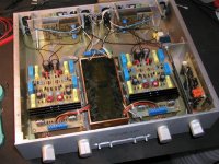
Looks like another Friday night and not much is going on on the forum (at least in the Dorkus' department). The guys from Portugal are getting wild posting Borberly circuits and since nobody really said anything about construction of the preamp I will post some pictures of the unit I've done 10 years ago. It had a nice switching capabilities, dual mono setup and remote volume.
I understand that the thing Dorkus is planning will be different, however, maybe some people would decide only on two channels and might take some inspiration from here.
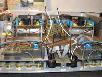
As you see power supply takes 2/3 of the space. There are two separate transformers which are potted and shielded with copper enclosure. Regulators for ea. channel are on opposite sides.
The active circuitry is at the back.
I understand that the thing Dorkus is planning will be different, however, maybe some people would decide only on two channels and might take some inspiration from here.
As you see power supply takes 2/3 of the space. There are two separate transformers which are potted and shielded with copper enclosure. Regulators for ea. channel are on opposite sides.
The active circuitry is at the back.
Attachments
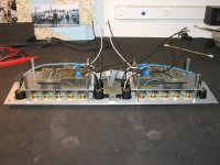
The heart of the preamp is the back pannel. Input and output jacks are mounted there. All the switching is done by relays mounted directly to the jacks and PCB, no wires. Right above the relay board is the metal plate which holds the active circuit. It is potted (I wouldn't do it now but back then I thought that potting would damp vibrations and allow even heat distribution). Beside the active block there is another board wich holds 10 relays which allow to switch the gain of the preamp from 10 dB to 20 dB by changing the feedback resistors. There is more space here and I was planning on mounting additional 2 boards above for active crossover. I never did it. However, vertical mounting of the boards allows for better use of space and shorter connections.
Attachments
i will post some pics of the integrated amp i built last year. it didn't turn out quite as well as i hoped it would (it has a trace of hum and is on the bright side, possibly due to the tinned PCBs i got), but it still sounds quite excellent (better than the Krell integrated my friend has IMHO) and works very well. the construction is not too shabby either, it even has full remote control. 
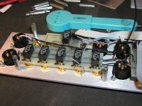
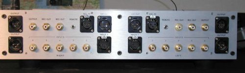
Here is the picture of the switching circuit. The relays are switched by rotary switches on the front panel. No logic, no fancy stuff. The volume is of a shunt type, 22k resistor in series, after that motorized Alps to the ground. Some with a quick eye (Apogee?) might notice that there is no AC connection on the back panel. The reason for that is that the back panel is divided for left and right side which contain corresponding inputs and outputs. I didn't want to run AC lines close to sensitive audio circuitry, so I placed the socket on the bottom directly beside the transformers.
Attachments
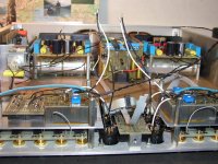
Those pictures might quite well fit the Pass Gallery because the active circuit I used was A75 front end. You can see the way I placed the big electrolytics under the regulators boards. The regulators were taken from ML23.5. The frame for the chassis is made of two aluminum slabs, 1/2" thick, on both sides. The front and back panels (1/8") are screwed to them as well as bottom and top (1/4").
Attachments
Motorised pot
HPotter, I'm currently upgrading a preamp to include remote volume control. However, the only circuit I have found that uses standard RC5 type infrared codes to drive a motorised pot is a ready built unit from Michael Percy Audio for $100. This seems very expensive; could you post more details of the arrangement you have used in your preamp?
Thanks,
TRWH.
Beautiful construction!
HPotter, what a nice piece of work. Makes me wonder how I could improve the looks of my own projects. Would you care to give some advice?
How did you get the brushed finish on the aluminium? What about the lettering on the front panel, how was that made? Finally: where did you find those good looking control knobs?
Thanks,
Pekka
AC bottom feed
quote: "I didn't want to run AC lines close to sensitive audio circuitry, so I placed the socket on the bottom directly beside the transformers". Mark Levinson pre-amp (e.g. 38S) also has bottom feed AC. Yours was built 10 years ago ... so, they were copying you?!
quote: "I didn't want to run AC lines close to sensitive audio circuitry, so I placed the socket on the bottom directly beside the transformers". Mark Levinson pre-amp (e.g. 38S) also has bottom feed AC. Yours was built 10 years ago ... so, they were copying you?!
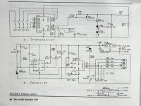
The circuitry in remote control setup comes from 2/91 Audio Amateur. It is slightly modified application note from Plessy Semiconductors of GB. The transmitter is powered by 9V battery and later I used learning remote from Sony.
Aluminum finish is done on belt sander with 150 grade belt and later clear anodized. Lettering is done by dry transfer from Letraset. You can buy sheets with different types of letters in graphic supply stores. The nice knobs I bought in surplus store and they come from Classe Audio preamps.
Regarding AC socket placement I don't know who was first but it seemed like pretty obvious choice to me. Below is schematic for remote. I don't knoe if the parts are still available.
Attachments
remote control kit
if you are lazy and don't want to build your own IR receiver circuit, there is also this kit:
http://www.electronickits.com/kit/complete/elec/ck1608.htm
it is not cheap either ($42) but better than the percy kit, which is a terribly overpriced. (nothing against m. percy, he is my #1 source of "audiophile" parts.)
- Status
- This old topic is closed. If you want to reopen this topic, contact a moderator using the "Report Post" button.
- Home
- Amplifiers
- Solid State
- Son of Dork: Chassis and Construction