Transformer output usually placed in tube amps, to convert speaker impedance towards tube high voltages.
In front of me now lies a solid state power amp, no-feedback design, voltage is 0---+50V, but the output is using transformer, in push-pull mode. The final transisors are mosfets, driven by small driving transformer (the designer sure likes transformer)
Big problem with the amp. When tested with pink noise, the curve is flat. Played with pop music, the sound is very good. But if played with piano sound (about 400-600hz), the sound becomes distorted, even in very low volume.
At first I suspect the driver. Trace the signal with 500hz test tone, all signals are good sinusoidal until gates of final mosfet. In the gates, the sinusiodal are good. but in the Drain of the final mosfets (which drive the final output transformer), the sinusoidal becomes distorted. Looking at the output with scope, (speaker attached), the sinusoidal in the speaker is somehow not a good sinusioidal.
How can I fix this? Is it possible that the no-good part is the final transformer itself? Oscilating at 500hz?
Very bad to drive transformer in push pull mode (like a tube amp).
Especially with an asymetrical signal like a piano.
The core 'walks' to one side and then distorts.
Cheap car stereo amps had this problem big time.
Properly designed amps will run from ±V supplies before being connected to the transformer (McIntosh).
It is also OK to use a cap coupled single voltage supply to drive a transformer.
Very bad to drive transformer in push pull mode (like a tube amp).
Especially with an asymetrical signal like a piano.
The core 'walks' to one side and then distorts.
Cheap car stereo amps had this problem big time.
Properly designed amps will run from ±V supplies before being connected to the transformer (McIntosh).
It is also OK to use a cap coupled single voltage supply to drive a transformer.
Thanks for the clue. But I cannot capacitor coupled the transformer and driving mosfet. The mosfet has steady bias, about 60mA. How can I cap coupled, but still have bias?
I think this kind of behavior is exactly what you should expect from such a nonsense design
MOSFETs show pretty non-linear transfer characteristics and when they are operated open-loop in such a flawed topology, they will add lots of asymmetric distortion to any asymmetric signal and this is potentially a source of DC applied to the transformer, that would require a *huge* gap to handle it
Note that audio waveforms are almost allways of asymmetric nature even if they are high-pass filtered to remove any residual DC. Sometimes one side has half the peak amplitude than the other side of the waveform [Look at piano waveforms with the oscilloscope]
I think the simplest way to cure that problem is to add some feedback to linearise the circuit and reduce the DC error seen by the transformer
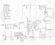
I cannot jigsaw the core to put gap, or put C between mosfet and core. I attach the schematic, maybe it will help you guys helping me.
I think about giving RLC (like the one used in speaker to flatten impedance curve). Putting this in output windings do not help at all. Will putting in both push-pull windings will help?
I think about giving RLC (like the one used in speaker to flatten impedance curve). Putting this in output windings do not help at all. Will putting in both push-pull windings will help?
Attachments
No matter how big a closed iron core! It can be saturated by some 100 mA at n*100 turns. Even my SU175 (15 kg mass) core. No RLC network can help.
Feedback can be helpful, and it lowers the output impedance too, wich is now very high. Additionally, you should mach the transistors by transfer admittance.
BTW: this is a common source class AB amplifier. Without feedback, it must distort.
An idea: if I were You, I would connect speaker directly to drains. Smaller transformator, better coupling at high freq.
Just a stupid question :
Is this schematic from an audio amplifier or from a switched mode power supply?. It looks like a push-pull SMPS with its control IC and its pulse transformer
The only way to get this topology to work properly is to ensure no DC at all is applied to the transformers. In SMPSs applications this is acomplished by using the same duty cycle for both sides and adding some dead time to allow small errors to self compensate. In audio applications you have to sense the voltage applied to the transformer, integrate it and compensate for DC errors introduced by non-balanced distortion components [removing bias to make it work in class B would also help in reducing DC applied to the transformer, this is the same as adding dead time on SMPS applications, but distortion wiil increase a lot, specially since there is no feedback at all]
As you all can see, the output is only secondary coil. This secondary coil is directly connected to the speaker. I've tried putting RLC in this, no effect at all. How about putting this RLC between drain and +Vcc (crossing primary coils). Will it help?No RLC network can help.
Feedback can be helpful, and it lowers the output impedance too, wich is now very high. Additionally, you should mach the transistors by transfer admittance
How can I make feedback with the existing topology? I cannot put some wire into the core.I think the simplest way to cure that problem is to add some feedback to linearise the circuit and reduce the DC error seen by the transformer
That would be ZEN V-7R. But right now I want to troubleshoot the existing problem.An idea: if I were You, I would connect speaker directly to drains. Smaller transformator, better coupling at high freq.
Mind telling me why is that? And how to apply feedback in the existing topology?BTW: this is a common source class AB amplifier. Without feedback, it must distort.
As in the schematic, the primary+final mosfets are designed TO HAVE bias about 60mA. Why is this so contrary to the fact that transformer do not handle DC? If I put blocking cap between drains and transformer, I dont think the whold system would work. Any suggestion on how to block DC, but still have bias flowing at the mosfets?The only way to get this topology to work properly is to ensure no DC at all is applied to the transformers
ZEN-V7R also have big bias with this primary. But the output is different, they are from the drain, like Pafi suggested. This one has output from secondary. Is that different?
I think this kind of behavior is exactly what you should expect from such a nonsense design.
MOSFETs show pretty non-linear transfer characteristics and when they are operated open-loop in such a flawed topology, they will add lots of asymmetric distortion to any asymmetric signal and this is potentially a source of DC applied to the transformer, that would require a *huge* gap to handle it
You are right, EVA. The design is non feedback. The NJM386 is just a 15V power audio IC. It has its feeback loop inside, about 20x. But from there, there is no feedback at all from the outputs, as you can see, the output is just secondary windings floating.
Plus the nonlinearity of the mosfet, operating in non feedback.
Making more bias will help or make it alot worse due to DC? Mosfets needs high bias to be linear, dont they? But the Core doesnt like DC at all. This is confusing situation.
How about this. I put gate resistor about 1k, and put feedback from drain to gate about 10k (gain =10x), like Mr.Pass uses on Zen. That is to make sure the mosfets only working in 10x gain, not more. Will this help?
I'm still thinking about how to add feedback without changing the topology  . The main problem arises because the circuit shows non-balanced transfer characteristics and this means that the error-corrected gate driving signal required to get a balanced output will be itself unbalanced, so it can't be applied through a drive transformer. How about driving the gates from op-amps?
I think that adding local feedback to the MOSFETs will help curing the problem so I recommend trying it. It may also require to add more turns to the secondaries of the drive transformer so more drive voltage is available
About transformers and DC : The transformer only sees the sum of the DC components applied to both primeries. It sees no net DC at all as long as equal DC currents flow through both primaries but in opposite directions [they 'cancel out'], so increased biasing by itself shouldn't cause the transformer to saturate. But when DC currents aren't of the same value or don't flow in opposite directions, the net difference [bias imbalance or unbalanced distortion products] is effectively applied to the transformer. A gapped design may withstand some tens of mA of imbalance without saturating. An ungapped design may saturate witn imbalances as low as 1mA
. The main problem arises because the circuit shows non-balanced transfer characteristics and this means that the error-corrected gate driving signal required to get a balanced output will be itself unbalanced, so it can't be applied through a drive transformer. How about driving the gates from op-amps?I think that adding local feedback to the MOSFETs will help curing the problem so I recommend trying it. It may also require to add more turns to the secondaries of the drive transformer so more drive voltage is available
About transformers and DC : The transformer only sees the sum of the DC components applied to both primeries. It sees no net DC at all as long as equal DC currents flow through both primaries but in opposite directions [they 'cancel out'], so increased biasing by itself shouldn't cause the transformer to saturate. But when DC currents aren't of the same value or don't flow in opposite directions, the net difference [bias imbalance or unbalanced distortion products] is effectively applied to the transformer. A gapped design may withstand some tens of mA of imbalance without saturating. An ungapped design may saturate witn imbalances as low as 1mA
Eva!
I agree with you at almost every points exept saturation current:
I(u,l,n)=l*B/u/n where u is permeability, l is the average length of magnetic circle.
Let's have a 200 turns primer, and a relative permeability of 10000:
Isat=0.1m*1T/10000/1,25*10^-6/200=40 mA
If You use a single 0,1mm air gap, current will be approximately
Isat=0.0001*1T/1,25*10^-6/200=400 mA (the field concentrated in the gap.)
But You can use more air gap. At 1,6mm (2*0,8mm) gap the inductance will be 30mH (assuming 10cm^2 cross-section), wich sets 20 Hz lower limit at 4 ohm.
With this gap Isat will be 6.4A, wich must be enough.
And one more thing: DC could be arises even if transfer charasteristics was perfectly balanced. Integral(-pi/2..pi/2,(cos(t)+cos(2*t))^2) is greater than integral(pi/2..3*pi/2,(cos(t)+cos(2*t))^2).
In english: let's have a specific signal with zero DC! We apply a quadratic transfer function on it, than we get a signal with DC component. (Average voltage is greater in the positive half of period, than the negative one.)
lumanauw!
The transfer function in this circuit is something like this: I=v^2 at positive, and I=-(v^2) in negative. There is no linear domain.
"How about this. I put gate resistor about 1k, and put feedback from drain to gate about 10k (gain =10x), like Mr.Pass uses on Zen. That is to make sure the mosfets only working in 10x gain, not more. Will this help?"
This can make it much better, but I'm afraid it won't be enough at higher levels.
I'm planning a similar amp, but at Class-A operating point. This makes the transfer charasteristics absolutely linear (theoretically ). It will have local feedback, and drain-coupled. You said, it's ZEN V-7R? Well, then I will build a ZEN V-7R.
I agree with you at almost every points exept saturation current:
I(u,l,n)=l*B/u/n where u is permeability, l is the average length of magnetic circle.
Let's have a 200 turns primer, and a relative permeability of 10000:
Isat=0.1m*1T/10000/1,25*10^-6/200=40 mA
If You use a single 0,1mm air gap, current will be approximately
Isat=0.0001*1T/1,25*10^-6/200=400 mA (the field concentrated in the gap.)
But You can use more air gap. At 1,6mm (2*0,8mm) gap the inductance will be 30mH (assuming 10cm^2 cross-section), wich sets 20 Hz lower limit at 4 ohm.
With this gap Isat will be 6.4A, wich must be enough.
And one more thing: DC could be arises even if transfer charasteristics was perfectly balanced. Integral(-pi/2..pi/2,(cos(t)+cos(2*t))^2) is greater than integral(pi/2..3*pi/2,(cos(t)+cos(2*t))^2).
In english: let's have a specific signal with zero DC! We apply a quadratic transfer function on it, than we get a signal with DC component. (Average voltage is greater in the positive half of period, than the negative one.)
lumanauw!
The transfer function in this circuit is something like this: I=v^2 at positive, and I=-(v^2) in negative. There is no linear domain.
"How about this. I put gate resistor about 1k, and put feedback from drain to gate about 10k (gain =10x), like Mr.Pass uses on Zen. That is to make sure the mosfets only working in 10x gain, not more. Will this help?"
This can make it much better, but I'm afraid it won't be enough at higher levels.
I'm planning a similar amp, but at Class-A operating point. This makes the transfer charasteristics absolutely linear (theoretically
). It will have local feedback, and drain-coupled. You said, it's ZEN V-7R? Well, then I will build a ZEN V-7R. "But You can use more air gap. At 1,6mm (2*0,8mm) gap the inductance will be 30mH (assuming 10cm^2 cross-section), wich sets 20 Hz lower limit at 4 ohm."
Listening to a resistor are we?
A ported speaker with a big magnet may have impedance peaks of 100 ohms or more, 30mH is totally inadequate.
Cheap tube amps have similar problems for similar reasons.
Listening to a resistor are we?
A ported speaker with a big magnet may have impedance peaks of 100 ohms or more, 30mH is totally inadequate.
Cheap tube amps have similar problems for similar reasons.
Hi, all,
Thanks for the opinions. All of you seems to direct to one point, that is the non-linearity of the transformer when driven by open loop mosfet (while mosfet itself is non linear).
Putting the 10k+1k resistors in drain and gate will limit the AC loop of the driving mosfet about 10x. My question is, will this lower the gain of the overall power amp? Or it will stay the same gain as original (I dont want the power amp sound tobe weak)
Pafi, sorry for the wrong writings. It should be ZEN V7-T, not ZEN V7-R. T is the one who uses transformer primaries for CT inductance, R is still using hi-watt resistor.
Wondering, if anyone has the same problem with ZEN V7-T? Distorted piano sound?
Pafi, you seems to understand much about tranformer. How can I calculate minimum requirement (minimum inductance or resistance) for the ZEN V7-T? Mr Pass himself does not touch this in his article (can be seen in Passdiy). He just use ordinary 120V+120V of 300VA primaries. If I want to DIY this load CT inductance, not using power transformer primaries, how can I calculate the requirement (toward voltage and speaker load)? What will be the number of turns and sizes of the magnet wire?
Thanks for the opinions. All of you seems to direct to one point, that is the non-linearity of the transformer when driven by open loop mosfet (while mosfet itself is non linear).
Putting the 10k+1k resistors in drain and gate will limit the AC loop of the driving mosfet about 10x. My question is, will this lower the gain of the overall power amp? Or it will stay the same gain as original (I dont want the power amp sound tobe weak)
EVA, I dont understand this. Care to explain more?The main problem arises because the circuit shows non-balanced transfer characteristics and this means that the error-corrected gate driving signal required to get a balanced output will be itself unbalanced, so it can't be applied through a drive transformer
Also dont understand this. Quadratic comes from mosfet transfer function? If we replace the final transistor with bipolars, will it more linear?The transfer function in this circuit is something like this: I=v^2 at positive, and I=-(v^2) in negative. There is no linear domain.
Pafi, sorry for the wrong writings. It should be ZEN V7-T, not ZEN V7-R. T is the one who uses transformer primaries for CT inductance, R is still using hi-watt resistor.
Wondering, if anyone has the same problem with ZEN V7-T? Distorted piano sound?
Pafi, you seems to understand much about tranformer. How can I calculate minimum requirement (minimum inductance or resistance) for the ZEN V7-T? Mr Pass himself does not touch this in his article (can be seen in Passdiy). He just use ordinary 120V+120V of 300VA primaries. If I want to DIY this load CT inductance, not using power transformer primaries, how can I calculate the requirement (toward voltage and speaker load)? What will be the number of turns and sizes of the magnet wire?
This is a very common topology for (cheap) Public Address amplifiers that have a 100V output (Europe/Asia) or 70V output (USA). Most of them use an output transformer with center tapped primary connected to a relatively low DC supply. Often just 12/24/48V because the amplifier must also run on batteries for use in cars, boats or with emergency power supplies. The output transformer is a requirement in order to get such a high voltage output, but also for safety. If the amplifier is grounded the output is still floating, so you can safely touch ONE output terminal.
Most of these amplifiers use BJTs in the output and have feedback applied from a separate transformer winding that is grounded on one end. The transformer is gapped and in most cases that is good enough to not even bother about DC balancing. They only have a preset for bias current.
Steven
Most of these amplifiers use BJTs in the output and have feedback applied from a separate transformer winding that is grounded on one end. The transformer is gapped and in most cases that is good enough to not even bother about DC balancing. They only have a preset for bias current.
Steven
There are some small but very important differences between this topology and classic PA amplifiers topology :
- PA ones use feedback so unbalance due to bad linearity and asymmetric signals is corrected to prevent transformer saturation
- PA ones drive the output transistors directly from op-amps or other transistors [DC coupled], so the unbalanced base drive currents required to correct device non-linearities with asymmetric signals are allowed
Anyway, without any DC balancing mechanism, transformer saturation is almost unavoidable when those amplifiers are driven into hard clipping with asymmetric signals
- Status
- This old topic is closed. If you want to reopen this topic, contact a moderator using the "Report Post" button.
- Home
- Amplifiers
- Solid State
- Transformer output solid state