I am building a single supply (24V) preamp and amplifier circuit that uses about 8 op amps for active filters and 4 LM3886 amplifier IC's (High and Low Bridged Outputs).
What is the best way to create a steady mid-rail voltage (VCC/2) for a reference voltage (also known as virtual ground) for the opamps and LM3886 IC's?
At the moment, I am trying an op amp follower circuit similar to the one shown on page 2 of this document http://www.analogzone.com/avt_0806.pdf (i originally didnt have the small resistor on the output and got oscillations from the op amp. the small 47R resistor fixed this)
I am using an LM324 op amp for the follower. (have a spare one available on the board). Can I also add a large electrolytic cap (68uF) to the follower output for filtering/regulation?
Virtual PS ground
You can use an LM317/LM337 pair (positive and negative regulators). The input to the positive and negative rails go to the appropriate regulator input. The grounds are tied together -- and this is your virtual ground. In fact, for the best results I have used two LM317's and two LM337's -- allowing for the overhead in each. (As described in Audio Amateur sometime in the early 1990's). Make sure to bypass the regulators as shown in the National Semi applications notes and use the appropriate resistors to set the output voltage. I use this technique (beefed up with some power transistors) to derive +/0/- from an old Heathkit regulated power supply and it works fine.
You can use an LM317/LM337 pair (positive and negative regulators). The input to the positive and negative rails go to the appropriate regulator input. The grounds are tied together -- and this is your virtual ground. In fact, for the best results I have used two LM317's and two LM337's -- allowing for the overhead in each. (As described in Audio Amateur sometime in the early 1990's). Make sure to bypass the regulators as shown in the National Semi applications notes and use the appropriate resistors to set the output voltage. I use this technique (beefed up with some power transistors) to derive +/0/- from an old Heathkit regulated power supply and it works fine.
I have always had good luck with a simple pair of
resistors, equal value, set up as a divider to form
a voltage halfway between v+ and ground. Then
put a nice big capacitor from the center point (+)
to ground (-).
Typical resistor values would be a few K and capacitor
maybe 1000 uF.
resistors, equal value, set up as a divider to form
a voltage halfway between v+ and ground. Then
put a nice big capacitor from the center point (+)
to ground (-).
Typical resistor values would be a few K and capacitor
maybe 1000 uF.
Hi Nelson - is this as simple as it sounds? One cap tied between the virtual ground and the real ground? (Just want to make sure I understand your comment correctly.)
Other schematics I've seen typically seem to show two caps - from virtual ground to B+ and ground respectively.
Other schematics I've seen typically seem to show two caps - from virtual ground to B+ and ground respectively.
Another very simple solution is TI's TLE2426 rail splitter. Available in a TO-92 case which takes up less space than a pair of resistors and a big cap.
se
se
The TLE 2426 is awesome for when voltages are very low... for instance a virtual split rail with resistors from a 9V battery into a common cmoy, will often act up long before the battery is flat, simply because the voltage drop on each rail pulls it out of the operating zone, and suddenly you have two diffirent voltages, despite useing a resistor divider....
Member
Joined 2009
Paid Member
One way to think of the virtual earth is that of a bridge circuit. The load is 'driven' from both ends, one by the amplifier playing music, the other end by an amplifier with a dc output. The reason I mention this is that you realize that the quality of the signal through the load depends on what is connected to both ends of the load. You might have a fancy amplifier on one end and a 'cheap' i.c. making your virtual earth on the other end - which doesn't make a lot of sense.
From this perspective the simple two (good quality) caps, two resistors approach might be preferred. If you size the resistors so that they can't flow enough current to damage the speaker you have a kind of simple speaker dc protection.
Of course, you could just make two amplifiers and bridge them.
From this perspective the simple two (good quality) caps, two resistors approach might be preferred. If you size the resistors so that they can't flow enough current to damage the speaker you have a kind of simple speaker dc protection.
Of course, you could just make two amplifiers and bridge them.
Thanks for the feedback.
What might good starting points be for resistor values for a 2050 T-amp? I've seen 4k7 used in several schematics? It seems that 220uf Caps are popular in this position?
What might good starting points be for resistor values for a 2050 T-amp? I've seen 4k7 used in several schematics? It seems that 220uf Caps are popular in this position?
Here it is: A Regulated Virtual Ground Circuit
All of them may be LM317 and LM377 which eliminates the need for matching.
All of them may be LM317 and LM377 which eliminates the need for matching.
An externally hosted image should be here but it was not working when we last tested it.
Not to different from this one.
Both takes in consideration that there is some current needing to flow via the ground, wich the simpler variants is relatively limited to cope with.
Ah You know what I mean.
But theese two makes it possible to get some out of it anyhow.
Yes, I found that and saved it. It is a glorified voltage divider with a little better stability. I was contemplating adding voltage regulation, but the LMxxxx do that for you.
I was just about to build it since I have a pair of trannys, but the regs are coming with the next load from Newark.
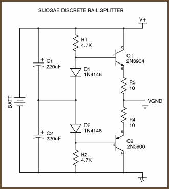
If I change my mind and build it, I will post the results. It may be good for some applications. Here is a slightly different rendition of the Discrete Rail Splitter:
http://www.hobby-circuits.com/circu...er-supply/882/discrete-virtual-ground-circuit
I was just about to build it since I have a pair of trannys, but the regs are coming with the next load from Newark.
If I change my mind and build it, I will post the results. It may be good for some applications. Here is a slightly different rendition of the Discrete Rail Splitter:
http://www.hobby-circuits.com/circu...er-supply/882/discrete-virtual-ground-circuit
Last edited:
I built it. Voltage division was almost perfect, even with 5% resistors, but the regulation is not good. Drawing 80mA, regulation was 22%. I used much bigger transistors that could handle much more.
I would go with the TI TLE2426, as Steve Eddy suggested, if the load is small. Otherwise, with the LM317/377 setup: 1.5A per rail with heatsinks!
I would go with the TI TLE2426, as Steve Eddy suggested, if the load is small. Otherwise, with the LM317/377 setup: 1.5A per rail with heatsinks!
Last edited:
A friend needed one to split his lab supply to dual for testing his F5.
It needs to be low impedance and capable of 1A or so.
I used to have something like that in post #12, but with TO3 Darlingtons and high bias.
But 1A bias is a bit much.
Those in post #8 are mostly for tiny current, and either have high impedance or stability issues.
So I looked at the 317_337 circuit in post #11.
It works, but a few changes were necessary for me :
I removed C2, C3 so that they wouldn't kill my voltage reference during start up and pass HF noise from the rails to the latter.
I used TLVH431 and a 10k trimmer instead of LM336, in case the Vref's of 317_337 are lower than 1.25V (datasheet says as low as 1.2V).
And of course a cap is necessary for the stability of the 431.
The 431 was trimmed so that V1-V2 ~ +30mV, so as to make sure the regulators have their required minimum working current.
R1 or R2 can be trimmed to centre the split, if necessary.
One can always use LT1083/1033 to get even more current.
Patrick
.
Attachments
Last edited:
Not entirely happy with the complicated circuit of the 317_337, I tried something else today.
I have some OPA544T lying around, so I set up one as a follower with +Vin at mid-rail.
Similarly to the VFB Opamp Based Virtual Ground Driver at
Virtual Ground Circuits
with the following changes :
Opamp = OPA544T
R1 = R2 = 10k
R3 = 0R
No C1; but with C2, C3 on the split rail outputs 2x 220µ.
Works fine, no stability issues.
Patrick
Resurrecting old thread as my search hit this one.
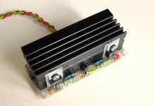
This is what I used a few times.
Basically a resistor based split with capacitors added would be just fine, if it wasn't for the DC imbalance due to the current sink to virtual ground by the circuitry that follows.
Can't drop resistor R1/R2 values as current drainage of the battery powered devices would suffer.
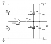
Essentially the BUF634 (any opamp in buffer mode would work - modulo being careful of DC current sink ability) is there only to provide DC ground.
The R3 value is such that DC imbalance is minimal given the DC current routed to virtual ground.
At audio signal level, basically anything to VG goes via C1||C2||C3||C4.
This is what I used a few times.
Basically a resistor based split with capacitors added would be just fine, if it wasn't for the DC imbalance due to the current sink to virtual ground by the circuitry that follows.
Can't drop resistor R1/R2 values as current drainage of the battery powered devices would suffer.
Essentially the BUF634 (any opamp in buffer mode would work - modulo being careful of DC current sink ability) is there only to provide DC ground.
The R3 value is such that DC imbalance is minimal given the DC current routed to virtual ground.
At audio signal level, basically anything to VG goes via C1||C2||C3||C4.
Attachments

No schematic, but a peek at the type of components suggests a circuit similar to the one at post #12.
- Home
- Amplifiers
- Solid State
- Creating the 'virtual ground' in a single supply preamp/amp circuit???