blu_line said:I managed to set the DC output voltage to 0 via an intergrator.
...
Another problems popped up.
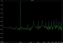
Did anyone ever do a FFT of an LT-Spice Sinus Source ?
I hoped they where clean, but they show 2nd and 3rd harmonics.
...
Hi Simon-Thijs,
I think I missed something. I thought you were interested in making a linear voltage to current converter as a transmitter and having a receiver doing the current to voltage conversion.
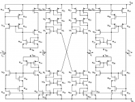
Now you have loaded your current output with R5 and with R10. The output impedance will not be high anymore. I hope the input of the receiver will have a much lower input impedance, otherwise the output current will just be attenuated by R5.
For what reason do you want to have a DC output voltage? The voltage will be determined by the DC level of the receiver (!) anyway, if that is a nice current input receiver. The Wilson current mirror has a reasonable good output voltage compliancy, i.e. the current will change only little because of changes in output voltage. I can imagine that you want to have a zero DC output current, but I think it is better to accept that there will be a small current offset and correct that at the receiver side, by a servo or otherwise.
I think you have more than a Watt of dissipation in Q11 and Q12. Maybe 100mA bias current is a bit too much for the output stage.
Be careful with the insertion of R19 and R20. Keep these small in value. Base current modulation of Q11 and Q12 will change the current through R19 and R20 and change the current ratio of Q1 and 2 versus Q11 and 12.
Notice this is a more or less linearized translinear circuit. It would be completely translinear by removing R19, 20, 21 and 22 and taking care of matching Q1 and 11 and Q2 and 12. Then the current ratio is just 1.
Keep the modulation index low to avoid a lot of distortion, so keep the AC current a fraction of the DC current. This is a closed loop of Vbe's with Q1, 2, 11 and 12 in a loop. This means That Ic1*Ic2=Ic11*Ic12 if all the resistors would be zero. Because Ic1=Ic2, forced by current sources, this gives that Ic11*Ic12 is constant. This is not a linear relationship, but a hyperbolic one. Doubling of Ic11 results in halving of Ic12. Using the resistors improves linearity, though.
I'm surprised by the FFT spectrum. It looks like there are frequencies visible that are non-harmonics, like 1.5kHz.

Steven
Thanks for the reply Steven
I used R5 only for simulationa and to see whether the V/I conversion is linear.
R10 is needed to serve as high impedant input for the DC Servo !
I played with R5 and R7 to see how the DC output would behave.
The minimum i got was 0v6 of DC offset.
So i put a DC servo in the circuit which, with just 45 mv, removes the DC offset. But i agree , it can be done on the receiver side as well !
And than could be seen by the FFT. When i drop the , the 2nd and 3rd harmonic rise with 20dB.
Thanks Steven !
grtz
Simon
Now you have loaded your current output with R5 and with R10. The output impedance will not be high anymore. I hope the input of the receiver will have a much lower input impedance, otherwise the output current will just be attenuated by R5.
I used R5 only for simulationa and to see whether the V/I conversion is linear.
R10 is needed to serve as high impedant input for the DC Servo !
I played with R5 and R7 to see how the DC output would behave.
The minimum i got was 0v6 of DC offset.
So i put a DC servo in the circuit which, with just 45 mv, removes the DC offset. But i agree , it can be done on the receiver side as well !
[ST : these resistors i put in to linearize the circuit much further.Be careful with the insertion of R19 and R20.
And than could be seen by the FFT. When i drop the , the 2nd and 3rd harmonic rise with 20dB.
Thanks Steven !
grtz
Simon
- Status
- This old topic is closed. If you want to reopen this topic, contact a moderator using the "Report Post" button.